


- In Situ Preparation of Gel Polymer Electrolytes for WO3/NiO Electrochromic Devices
Jin-Sol Ra and Seog-Jin Jeon†

Department of Polymer Science and Engineering, Kumoh National Institute of Technology, Gumi, Gyeongbuk 39177, Korea
- In situ 형성 고분자 젤 전해질 기반 WO3/NiO 전기변색소자의 제작
라진솔 · 전석진†
국립금오공과대학교 고분자공학과
Reproduction, stored in a retrieval system, or transmitted in any form of any part of this publication is permitted only by written permission from the Polymer Society of Korea.
Recently, with the expansion of the application of electrochromic devices (ECDs) to smart eyewear, the demand for safety in ECDs has increased. Gel polymer electrolytes (GPEs) have less risk of leakage and high ionic conductivity, making them suitable for smart eyewear. In this study, ECD was fabricated by in situ curing an electrolyte precursor based on poly(ethylene glycol) methyl ether methacrylate (PEGMEMA) monomer and poly(ethylene glycol) dimethacrylate (PEGDMA) cross-linker between WO3 and NiO electrochromic layers. Electrochromic properties of ECDs, optical density and response time, and the ionic conductivity of the electrolyte tended to improve when the ratio of PEGMEMA to PEGDMA was 10:1 but showed degraded properties at higher or lower ratios. The result can be understood because the density of the network due to the cross-linker content affects the cross-linking efficiency and the movement of ions and suggests the need for optimizing the cross-linker content for the in situ preparation of GPEs.
최근 전기변색소자의 스마트 아이웨어 등으로의 응용에 의해 안전성에 대한 요구가 보다 높아지고 있다. 고분자 젤 전해질은 누액의 위험이 적어서 안전하고, 높은 이온전도도를 나타내어 스마트 아이웨어의 응용에 적합하다. 본 연구에서는 poly(ethylene glycol) methyl ether methacrylate(PEGMEMA) 모노머와 poly(ethylene glycol) dimethacrylate (PEGDMA) 가교제 기반의 전해질 전구체를 WO3 층과 NiO 층의 사이에서 in situ 경화하여 ECD를 제작하였다. 제작된 ECD의 광학밀도와 반응속도 등 전기변색특성과 전해질의 이온전도도는 PEGMEMA와 PEGDMA의 비율이 10:1 일 때 가장 우수한 특성을 나타내었으며 이보다 높거나 낮은 비율에서는 저조한 특성을 나타내었다. 이 결과는 가교제의 함량에 의한 네트워크의 조밀함이 가교의 효율성 및 이온의 이동에 영향을 주기 때문인 것으로 이해할 수 있고, 고분자 젤 전해질의 in situ 형성에서 가교제 함량 최적화의 필요성을 제시한다.
In situ curing of gel polymer electrolytes (GPE) improves work efficiency and interfacial contact during the ECD manufacturing process. GPEs based on PEGMEMA monomer and PEGDMA cross-linker were in situ prepared in WO3/NiO electrochromic devices and their electrochromic properties were evaluated. The monomer content was optimized based on the optical density, response speed, and ionic conductivity.
Keywords: gel electrolytes, in situ preparation, electrochromic devices, WO3, NiO.
This research was supported by National University Development Project (2021).
The authors declare that there is no conflict of interest.
Electrochromic devices (ECDs) have been applied to applications that need selective light modulation, such as smart windows and smart mirrors, due to their ability to modulate light at a large extent by low applied voltage.1,2
Recently, their application has been extended to smart eyewear, such as smart sunglasses.3,4
Since the eyes are particularly sensitive and the most vulnerable to damage among human organs, ECDs for eyewear require not only high performance but also high stability.
Electrolytes for ECDs are classified into liquid electrolytes, solid electrolytes, and gel polymer electrolytes (GPE), and they have distinct characteristics in terms of performance and stability.5-7 Liquid electrolyte has high ionic conductivity of more than 10-3 S/cm. However, there is a risk of leakage, and it may evaporate when used for a long time, causing a change in the performance of the device. On the other hand, the solid electrolyte is highly stable, but the low ionic conductivity of 10-6–10-8 S/cm2 and the contact issue need to be improved.8 GPE is a network of polymers containing solvents and lithium salt. It has a relatively high ionic conductivity of 10-4 S/cm, and its adhesive nature provides stable contact.9 It has the advantages of liquid and solid electrolytes, making it suitable for applications that require high performance and stability, such as eyewear. As polymers that constitute GPE, PEG,10-12 PMMA,13,14 and PVDF15,16 have been used. Among them, PEG has been widely used for GPE due to its high stability, low price, good electrochemical stability, and compatibility with lithium salt.12 Lithium salt interacts with the ethylene oxide group of the PEG polymer to form a stable complex, and Li+ ions are known to move through the complexing-dissociating process due to the movement of the PEG polymer chain.17,18 PEG functionalized with 2 or more acrylate groups can form GPE by photocuring and has been applied by in situ curing to ECD of PEDOT,19
PproDOT-Me210 electrochromic material, or WO3/ATO electrochromic material pair.20 On the other hand, little research has been done on the in situ formation and electrochromic properties of PEG-based electrolytes for WO3/NiO ECDs.
In this study, GPE precursor compositions were prepared using PEG-based monomer and cross-linker, poly(ethylene glycol) methyl ether methacrylate (PEGMEMA) and poly(ethylene glycol) dimethacrylate (PEGDMA), respectively. The prepared precursors were formed into GPE through in situ curing within ECDs with WO3 and NiO. The ECDs’ electrochromic properties were dependent on the cross-linker content, which was analyzed and optimized in terms of optical density, response time, and ionic conductivity.
Materials. Propylene carbonate, poly(ethylene glycol) methyl ether methacrylate (PEGMEMA, Mn = 500), and poly(ethylene glycol) dimethacrylate (PEGDMA, Mn = 550) were purchased from Sigma Aldrich (USA). Lithium perchlorate was purchased from Acros (USA). Irgacure 2959 was purchased from TCI (Japan).
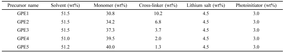
Preparation of Precursors for Electrolytes. Precursors for the in situ preparation of electrolytes are composed of monomer, cross-linker, lithium salt, photoinitiator, and solvent, as shown in Table 1. PEGMEMA, PEGDA, lithium perchlorate, irgacure 2959, and propylene carbonate were used as a monomer, cross-linker, lithium salt, photoinitiator, and solvent, respectively. Monomer to cross-linker ratio in the precursors was controlled 3:1, 5:1, 10:1, 20:1, and 30:1, and they were designated as GPE1, GPE2, GPE3, GPE4, and GPE5, respectively, as shown in Table 1.
ECD Fabrication. WO3 and NiO were deposited on 5 × 5 cm ITO glass substrates by e-beam evaporation. Window shape 100 μm thick double-sided tape was attached to NiO coated ITO glass, and the electrolyte precursor solution was poured on the NiO surface. WO3 coated ITO glass was put on NiO coated glass, and the precursor moved out from the effective area (4 × 4 cm) was removed. Finally, the device was UV cured for 5 min.
Characterization. The thickness of electrochromic layers was measured using a stylus-type profilometer (AlphaStep, D-500, KLA-tencor, USA). Transmittance was measured with a transmittance meter (LS162, Linshang, China), and the time-dependent transmittance was measured using a UV-vis spectrometer (Flame, Ocean Optics, USA). The transmittance was obtained and averaged for a wavelength range between 380 and 760 nm. The cyclic voltammetry and ionic conductivity were obtained by a potentiostat (Zive SP1, WonA Tech, South Korea).
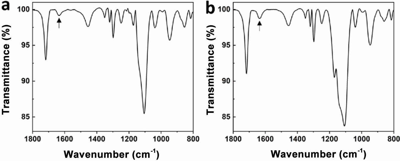
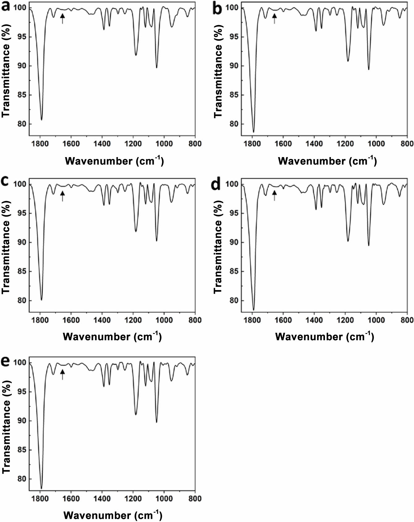
Cross-linking of Electrolytes. PEGMEMA and PEGDMA are monoacrylate and diacrylate and have an acrylate functional group. The C=C double bond of the acrylate group is broken by UV irradiation in the presence of an initiator, and curing progresses as it connects to other C=C double bonds. PEGMEMA has one acrylate, so it forms a linear polymer by polymerization, and PEGDMA has an acrylate group at each end, so it forms a cross-link to the two growing chains. Since the reactions proceed while consuming the double bonds of acrylate, the progress of curing can be confirmed through FTIR. The FTIR spectra of PEGMEMA and PEGDMA have a peak for the C=C double bond at 1630 cm-1, as shown in Figure 1. We cured the electrolyte by UV irradiation for 5 minutes, and the FTIR spectrum after UV irradiation is shown in Figure 2. In all electrolyte compositions, it was confirmed that the peak corresponding to the C=C double bond disappeared. Therefore, it was confirmed that curing progressed completely within 5 minutes.
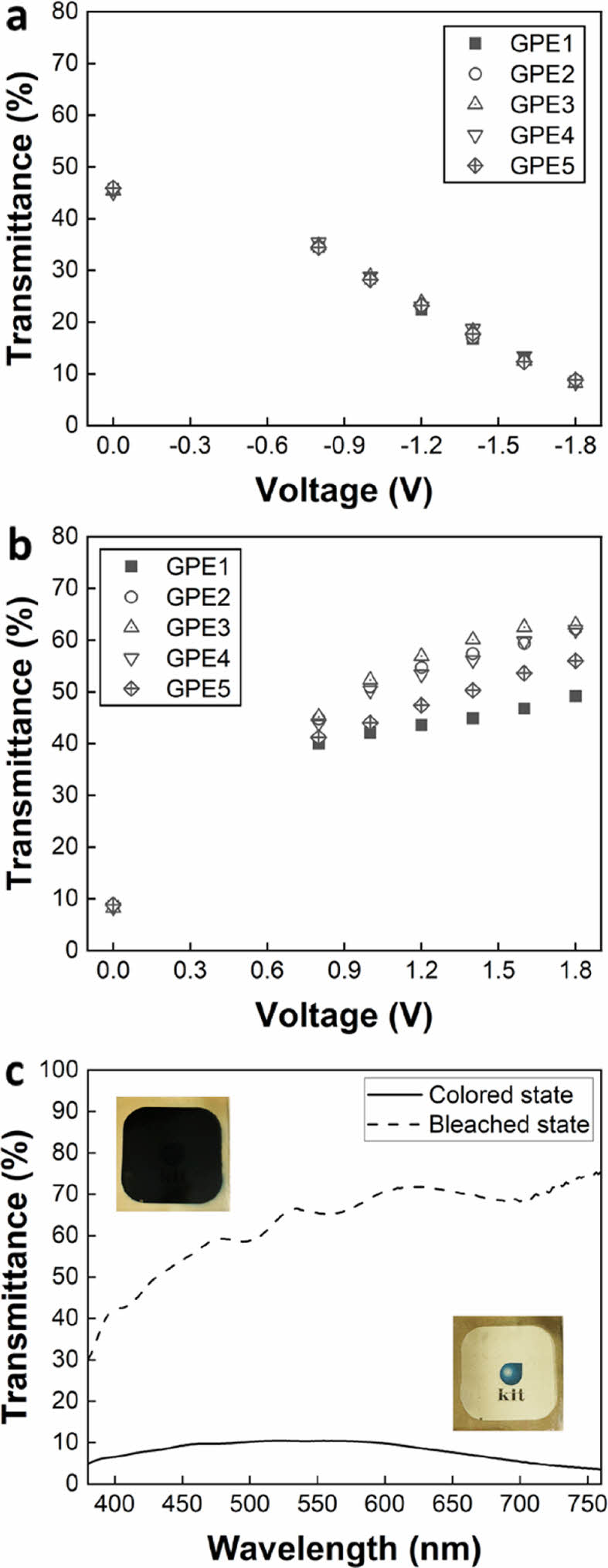
Optical Properties of ECDs. WO3 is a reductive electrochromic material colored by the insertion of Li+ ions and electrons. Conversely, NiO is an oxidative electrochromic material colored when Li+ ions and electrons are extracted. Therefore, WO3 and NiO are colored simultaneously for the cathodic scan, and are bleached simultaneously for the reverse scan, thereby maximizing the modulation of the transmittance of ECD. We fabricated the device by in situ curing the electrolyte precursor between the WO3 and NiO electrochromic layers and evaluated the transmittance of the fabricated ECDs.
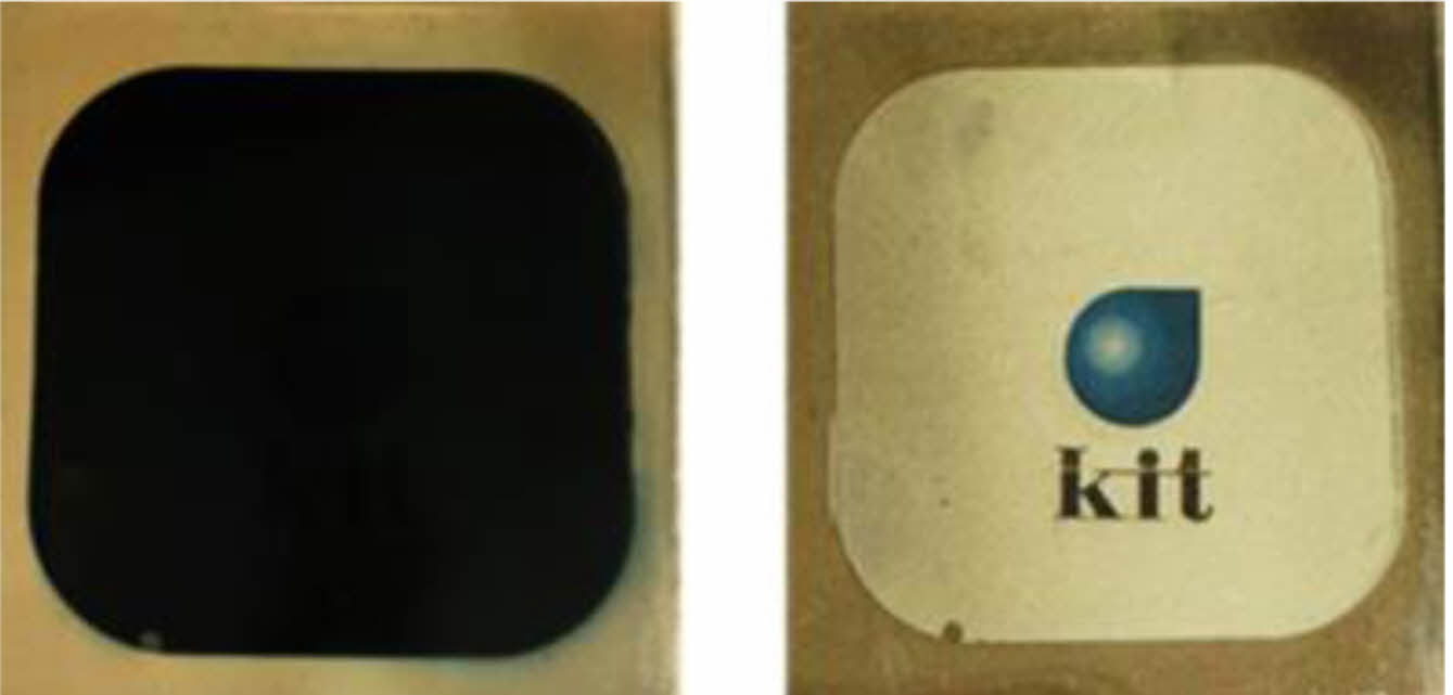
The transmittance of ECDs before applying voltage was similar for all samples at approximately 45%. A voltage was applied to each sample from -0.8 V to -1.8 V in 0.2 V increments, and after waiting a sufficient time, the transmittance at each voltage was measured. The transmittance during coloring showed a monotonic decrease as the voltage increased, and the trend was similar for all electrolyte compositions (Figure 3a and 3b). The transmittance at -1.8 V was 8.2 to 8.8%, with a slight difference. On the other hand, the transmittance in the bleached state was the lowest at 49.2% for GPE1, between 62 and 63% for GPE2-4, and 56% for GPE5. The transmittance for GPE3 wavelength was inserted as a representative example (Figure 3(c)). The color at the colored state of GPE3 was close to black (inset at the top of Figure 3c) due to the combination of the bluish color of WO3 and the brownish color of NiO. In the bleached state, it became transparent, allowing the logo on the background to be seen (inset at the bottom of Figure 3c).
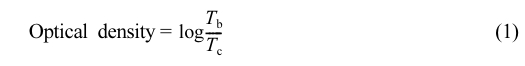
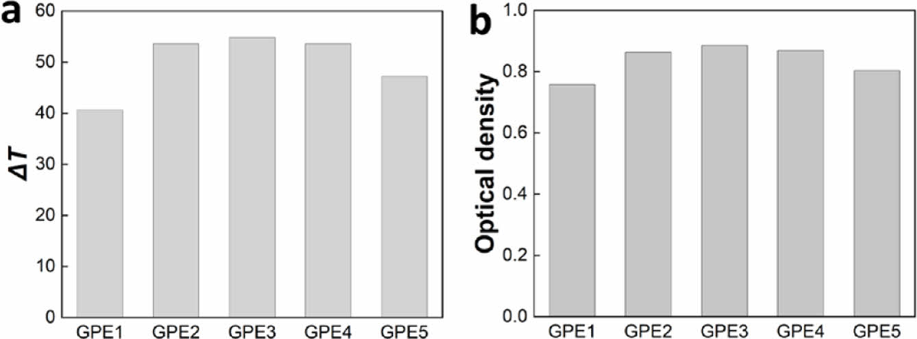
ΔT and optical density were calculated from the lowest transmittance in the colored state (Tc) and the highest transmittance (Tb) in the bleached state and are shown in Figure 4. ΔT is the difference between Tb and Tc, and optical density was calculated using the following equation.
The highest ΔT and optical density were observed in GPE3, showing 54.8% and 0.89, respectively.
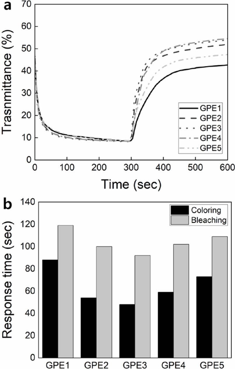
Response Speed of ECDs. Changes in transmittance over time were observed to measure the response speed of ECDs. The change in transmittance was investigated for 300 seconds of coloring at -1.8 V and 300 seconds of bleaching at 1.8 V (Figure 5(a)). During the coloring, all ECDs showed a similar trend in transmittance, and GPE2-4 responded slightly faster. To compare the difference in coloring response time, tc,90%, which is the time to reach 90% of the transmittance at 300 seconds, is shown in Figure 5(b). tc,90% showed 88 seconds in GPE1, then decreased to 48 seconds, the fastest in GPE3, and then increased again to 73 seconds in GPE5. To compare the difference in response time for bleaching, the time to reach 90% of the transmittance at 600 seconds, tb,90%, is compared and shown in Figure 5(b). tb,90% showed 119 seconds in GPE1, then decreased to 92 seconds, the fastest in GPE3, and then increased again to 109 seconds in GPE5. Regarding coloring and bleaching, changes in tc,90% and tb,90% showed similar trends. In coloring and bleaching, GPE1, with the highest PEGDMA content, showed the slowest response speed, and GPE3, with a PEGMEMA to PEGDMA ratio of 10:1, showed the fastest response speed.
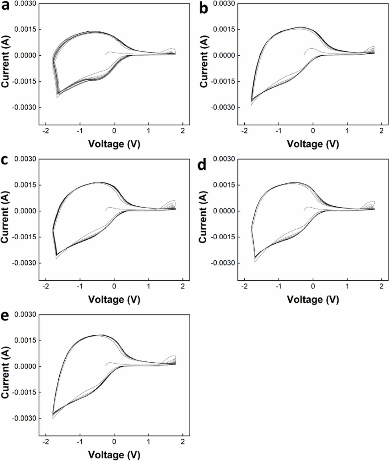
Electrochemical Properties of ECDs. Cyclic voltammetry (CV) was measured to compare the electrochemical properties of ECDs (Figure 6). The shape of the curve observed between -1.8 V and 0.5 V is the typical redox curve of WO3, and the redox curve of NiO appears weak between 1.2 V and 1.8 V.21
Each CV curve was measured for 20 cycles. For all electrolytes, the shape of the CV curve quickly stabilized in the initial cycle, and no significant change in the shape of the curve was observed with increasing cycle number.
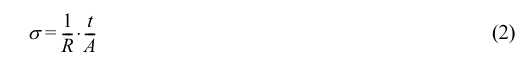
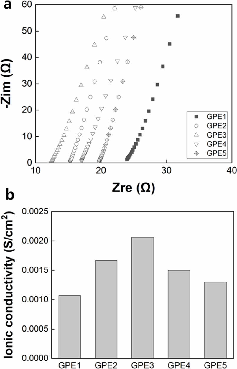
It can be speculated that the difference in density of the polymer network caused by the difference in the content of monomer and cross-linker in each electrolyte will affect ionic conductivity. Ion conductivity was calculated using the following equation. Resistance (R) was obtained through impedance measurement (Figure 7(a)), and the thickness (t) and effective area (A) of the electrolyte layer were substituted, respectively.
As shown in Figure 7(b), ionic conductivity was lowest in GPE1, which had the highest PEGDMA ratio, and increased as the PEGDMA content increased, reaching the highest in GPE3. As the PEGDMA content further increased, ionic conductivity decreased. The highest and lowest ionic conductivities were 0.00206 S/cm2 and 0.00107 S/cm2, respectively, observed in GPE3 and GPE1. It is speculated that the high ionic conductivity of 10-3 S/cm2 is due to the solvent content more than 50 wt%.
As the content of the PEGDMA cross-linker increases, the density of the polymer network in the electrolyte increases. Conversely, as the content of the cross-linker decreases, the density of the network is predicted to be reduced. For in situ polymerization, it has been reported that this tendency is associated with the formation of the thickness of the electrolyte film. Zhu et al. reported that as a denser network is formed, the diffusion of monomers is limited, but, on the contrary, when a sparse network is formed, the diffusion of monomers is limited due to the high mobility of the polymer chain, making it difficult to form a sufficient thickness.10
Therefore, there is an optimal composition of monomer and cross-linker that forms the sufficient thickness of the network.
We investigated ΔT, optical density, response time, and ionic conductivity of GPE with different cross-linker contents compared to monomer. As the cross-linker content decreased, all factors tended to improve, but it was confirmed that the maximum value was reached at GPE3, where the monomer-to-cross-linker ratio was 10:1, and then decreased. At cross-linker content higher than GPE3, the density of the network was too high, which might hindered the diffusion of monomers, preventing the electrolyte from forming a sufficiently thick film. It is also possible that the increased network density impeded the diffusion of Li ions. On the other hand, at a cross-linker content lower than GPE3, the density of the network was so low that the diffusion of monomers was affected due to the high mobility of the polymer chain, and the electrolyte was unable to form a sufficiently thick film, leading to a decrease in ΔT, optical density, response time, and ionic conductivity. If the thickness of the gel electrolyte is sufficient to fill the space between the electrochromic layers completely, it is expected that the gel network acts as a bridge between the electrochromic layers, allowing ions to move quickly. However, if the thickness of the gel electrolyte is not sufficient, empty areas where no gel is formed will be formed, which might prevent efficient transfer of ions and degrade entire electrochromic performances. From this, it can be seen that controlling the content of monomers and cross-linkers is important in the formation of in situ curable GPE, and it was confirmed that this can be optimized through various measurements.
|
Figure 1 FTIR spectra of (a) PEGMEMA; (b) PEGDMA. C=C double bond peak was indicated with an arrow. |
|
Figure 2 FTIR spectra of electrolytes after UV curing for 5 min: (a) GPE1; (b) GPE2; (c) GPE3; (d) GPE4; (e) GPE5. C=C double bond peak was indicated with an arrow. |
|
Figure 3 Transmittance of all samples at different voltages for (a) coloring; (b) bleaching; (c) Transmittance of GPE3 for coloring and bleaching at -1.8 and 1.8V, respectively. |
|
Figure 4 (a) ΔT ; (b) optical density comparison between electrolytes. |
|
Figure 5 (a) Time-dependent transmittance change for coloring and bleaching; (b) response time, tc,90% and tb,90%, comparison between electrolytes. |
|
Figure 6 CV curves for ECDs with (a) GPE1; (b) GPE2; (c) GPE3; (d) GPE4; (e) GPE5. |
|
Figure 7 (a) Impedance measurement; (b) ionic conductivity of electrolytes. |
We fabricated WO3/NiO ECDs by in situ curing PEGMEMA monomer and PEGDMA cross-linker based GPE precursors. ΔT, optical density, response time, and ionic conductivity were measured in ECDs using electrolytes with different cross-linker content compared to monomer, and the trends of these factors according to changes in cross-linker content compared to monomer were analyzed. All factors showed the poorest results in the GPE1 electrolyte with a monomer-to-cross-linker content of 3:1, while the results improved as the monomer content increased, and the GPE3 electrolyte with a monomer-to-cross-linker content of 10:1 showed the most improved results. When the monomer-to-cross-linker content ratio was higher than 10:1, all factors again showed poor results. During the in situ curing process, if the monomer content is lower than the optimal ratio, the polymer network is too dense, and the diffusion of monomers is hindered. Conversely, the high mobility of the polymer chain impedes the diffusion of monomers, resulting in this tendency. It is expected that the results of this paper can be applied to optimize the composition of various in situ curable GPEs and maximize the performance of ECDs.
- 1. Mortimer, R. J. Electrochromic Materials. Annu. Rev. Mater. Res. 2011, 41, 241-268.
-

- 2. Wang, J.; Lee, P. S. Next-Generation Multifunctional Electrochromic Devices. Acc. Chem. Res. 2016, 49, 1469-1476.
-
- 3. Lee, J. H.; Kim, H.; Hwang, J.-Y.; Chung, J.; Jang, T.-M.; Seo, D. G.; Gao, Y.; Lee, J.; Park, H.; Lee, S.; Moon, H. C.; Cheng, H.; Lee, S.-H.; Hwang, S.-W. 3D Printed, Customizable, and Multifunctional Smart Electronic Eyeglasses for Wearable Healthcare Systems and Human–Machine Interfaces. ACS Appl. Mater. Interfaces 2020, 12, 21424-21432.
-
- 4. Fu, H.; Tang, Y.; Zhan, F.; Zhang, L.; Zhan, W.; Dong, Y.; Li, W.; Zhang, C. Dual Polymer Electrochromic Sunglasses with Black to Anti-Blue-Ray Conversion Based on New Anti-Blue-Ray Transparent Polymer. Chem. Eng. J. 2023, 461, 141848.
-
- 5. Thakur, V. K.; Ding, G.; Ma, J.; Lee, P. S.; Lu, X. Hybrid Materials and Polymer Electrolytes for Electrochromic Device Applications. Adv. Materials 2012, 24, 4071-4096.
-
- 6. Alesanco, Y.; Viñuales, A.; Rodriguez, J.; Tena-Zaera, R. All-in-One Gel-Based Electrochromic Devices: Strengths and Recent Developments. Materials. 2018, 11, 414.
-
- 7. Rai, V.; Singh, R. S.; Blackwood, D. J.; Zhili, D. A Review on Recent Advances in Electrochromic Devices: A Material Approach. Adv. Eng. Mater. 2020, 22, 2000082.
-
- 8. Agrawal, R. C.; Pandey, G. P. Solid Polymer Electrolytes: Materials Designing and All-Solid-State Battery Applications: An Overview. J. Phys. D: Appl. Phys. 2008, 41, 223001.
-
- 9. Song, J. Y.; Wang, Y. Y.; Wan, C. C. Review of Gel-Type Polymer Electrolytes for Lithium-Ion Batteries. J. Power Sources 1999, 77, 183-197.
-
- 10. Zhu, Y.; Otley, M. T.; Zhang, X.; Li, M.; Asemota, C.; Li, G.; Invernale, M. A.; Sotzing, G. A. Polyelectrolytes Exceeding ITO Flexibility in Electrochromic Devices. J. Mater. Chem. C 2014, 2, 9874-9881.
-
- 11. Périé, C.; Mary, V.; Faceira, B.; Rougier, A. Colored Electrolytes for Electrochromic Devices. Solar Energy Mater. Solar Cells 2022, 238, 111626.
-
- 12. Feng, J.; Wang, L.; Chen, Y.; Wang, P.; Zhang, H.; He, X. PEO Based Polymer-Ceramic Hybrid Solid Electrolytes: A Review. Nano. Convergence 2021, 8, 2.
-
- 13. Vondrák, J.; Reiter, J.; Velická, J.; Sedlařı́ková, M. PMMA-Based Aprotic Gel Electrolytes. Solid State Ionics 2004, 170, 79-82.
-
- 14. Lee, H. J.; Lee, C.; Song, J.; Yun, Y. J.; Jun, Y.; Ah, C. S. Electrochromic Devices Based on Ultraviolet-Cured Poly(Methyl Methacrylate) Gel Electrolytes and Their Utilisation in Smart Window Applications. J. Mater. Chem. C 2020, 8, 8747-8754.
-
- 15. Hsu, C.-Y.; Lee, K.-M.; Huang, J.-H.; Justin Thomas, K. R.; Lin, J. T.; Ho, K.-C. A Novel Photoelectrochromic Device with Dual Application Based on Poly(3,4-Alkylenedioxythiophene) Thin Film and an Organic Dye. J. Power Sources 2008, 185, 1505-1508.
-
- 16. Nguyen, C. A.; Xiong, S.; Ma, J.; Lu, X.; Lee, P. S. Toward Electrochromic Device Using Solid Electrolyte with Polar Polymer Host. J. Phys. Chem. B 2009, 113, 8006-8010.
-
- 17. Müller-Plathe, F.; Van Gunsteren, W. F. Computer Simulation of a Polymer Electrolyte: Lithium Iodide in Amorphous Poly(Ethylene Oxide). J. Chem. Phys. 1995, 103, 4745-4756.
-
- 18. Meyer, W. H. Polymer Electrolytes for Lithium-Ion Batteries. Adv. Mater. 1998, 10, 439-448.
-
- 19. Ding, Y.; Invernale, M. A.; Mamangun, D. M. D.; Kumar, A.; Sotzing, G. A. A Simple, Low Waste and Versatile Procedure to Make Polymer Electrochromic Devices. J. Mater. Chem. 2011, 21, 11873.
-
- 20. Lee, M.; Son, M.; Chun, D.; Lee, C. S. Evaluation of Electrochromic Device Influenced by Various Formulation of Solid Polymer Electrolyte. Int. J. Precis. Eng. Manuf. 2021, 22, 189-199.
-
- 21. Wang, L.; Zhang, X.; Li, Y. A Novel Method for Performance Rejuvenation of WO3//NiO Electrochromic Devices: Lithium Ion Kinetic Behavior with Variable Cycling Temperature and Switching Voltage. ACS Sustainable Chem. Eng. 2023, 11, 13566-13573.
-
- Polymer(Korea) 폴리머
- Frequency : Bimonthly(odd)
ISSN 0379-153X(Print)
ISSN 2234-8077(Online)
Abbr. Polym. Korea - 2023 Impact Factor : 0.4
- Indexed in SCIE
 This Article
-
2024; 48(3): 312-317
Published online May 25, 2024
- 10.7317/pk.2024.48.3.312
- Received on Dec 26, 2023
- Revised on Feb 15, 2024
- Accepted on Feb 20, 2024
Services
- Full Text PDF
- Abstract
- ToC
- Acknowledgements
- Conflict of Interest
Introduction
Experimental
Results and Discussion
Conclusions
- References
Shared
Correspondence to
- Seog-Jin Jeon
-
Department of Polymer Science and Engineering, Kumoh National Institute of Technology, Gumi, Gyeongbuk 39177, Korea
- E-mail: sjjeon@kumoh.ac.kr
- ORCID:
0000-0002-3372-6532
Hyecheon Building(Room 601), #354, Gangnam-Daero, Gangnam-Gu, Seoul 06242, Korea
TEL : 82-2-568-3860, 561-5203, 569-3860 FAX : 82-2553-6938 E-mail: polymer@polymer.or.kr