


- Mesoporous Carbon Nanorod from Direct Templating Method and Its Application to Electric Double-layer Capacitor (EDLC) Electrodes
Hyunchul Kang, Kibum Hwang, Eunseon Shin, Jaekwang Kim, Sung Gyu Pyo† , and Songhun Yoon†

School of Integrative Engineering, Chung-Ang University, 221, Heukseok-Dong, Dongjak-Gu, Seoul 06974, Korea
- 직접 주형법을 이용한 메조다공성 나노막대형 탄소 재료의 합성과 고성능 전기이중층 캐패시터 전극으로의 적용
강현철 · 황기범 · 신은선 · 김재광 · 표성규† · 윤성훈†
중앙대학교 융합공학부
Reproduction, stored in a retrieval system, or transmitted in any form of any part of this publication is permitted only by written permission from the Polymer Society of Korea.
Using the self-assembly reaction between cationic surfactant and silicate solution, a direct templating method was investigated. After the addition of resorcinol and formaldehyde into the solution, the polymerization reaction was conducted and surfactant/silicate/polymer nanocomposite was prepared. After carbonization and following hydrofluoric acid etching, mesoporous carbon nanorod (MPCNR) particles were prepared. As-prepared material was applied into electrode in electric double-layer capacitors and various electrochemical analysis was carried out using the electrodes. Due to the well-developed mesoporosity and nanosized rod particles, a highly improved rate performance (low resistance in pores) and large double layer capacitance per area (17.4 µF cm-2) than the commercialized activated carbon electrode were observed, which was attributed to easy penetration through mesopores and optimized pore length for electrolyte transport.
양이온계 계면활성제와 실리케이트 용액의 자기조립 반응을 이용하여 기공 형성의 주형으로 이용하고 여기에 레소시놀-포름알데하이드를 투여한 후 고분자화 반응을 통하여 계면활성제/실리케이트/고분자 나노 복합체를 제조하였다. 제조된 나노 복합체를 고온에서 탄화하고 이를 불산으로 에칭하여 메조다공성 나노막대형 탄소 재료를 성공적으로 제조하였다. 제조된 메조다공성 나노 막대 탄소 재료를 전기이중층 캐패시터 전극으로 적용하였으며, 다양한 전기화학 실험을 통하여 그 성능을 평가하였다. 이 결과 잘 발달된 메조 기공 내부의 원활한 이온 전달 특성 및 나노 막대에서의 최적화된 기공 길이로 인해, 기존의 활성탄 재료보다 매우 우수한 속도 특성(낮은 기공 저항) 및 높은 면적당 캐패시턴스(17.4 μF cm-2)를 갖는 전기이충층 캐패시터 전극 재료를 제조할 수 있었다
The surfactant/silicate/polymer nanocomposite was used to prepare a mesoporous nanorod-type carbon material due to the well-developed inner mesopores and the optimized pore length in the nanorods. It was possible to manufacture an electric double-layer capacitor electrode material having very superior speed characteristics and high capacitance per area than conventional activated carbon materials.
Keywords: mesoporous carbon nanorods, electric double layer capacitors
This work is supported by the National Research Foundation of Korea (NRF) grant funded by the Korea government (MSIP) (No. 2019R1A2C1011175). Also, this work is supported by the Chung-Ang University research scholarship grant 2019 (assistant researcher A).
Recently, a considerable research effort has been made for the preparation of porous carbons, whose application has been occurred in the field of electrode materials for electric double-layer capacitor (EDLC), adsorbents for large molecules and catalyst supports.1 The electric double-layer located at the interface between electrode and electrolyte was utilized for charge storage in EDLC. For the purpose of a large charge storage ability in porous carbon electrodes, a high surface area was essential since the charge storage capacity (expressed as capacitance) is proportional to surface area. Also, the rate capability can be a significant consideration for practical EDLC application, since an efficient charging within the surface at electric double-layer is required.2,3 The imperfect accessibility of electrolyte within electrode surface has been observed particularly at high current or large scan rate condition, under which electrolyte transport becomes retarded during the current transient. This feature is more aggravated when pores are narrow, long and irregularly connected, where electrolytes cannot transport into the inner region and the exposed surface cannot be accommodated for charge storage.3 Hence, a large surface area with large pores, short length and good connectivity can be the ideal characteristics for EDLC electrode.4 On aspect of particle size, carbons of smaller size particles are favored in that ion penetration depth is shorter in smaller particles.
In our previous reports, direct templating method using self-assembled surfactant/silicate micelles as template has been investigated.5-7 After polymerization reaction using precursors such as resorcinol and formaldehyde, surfactant/silicate/polymer nanocomposite was prepared. By following carbonization and hydrofluoric acid etching, mesoporous carbon materials have been prepared. Especially, the influence of surfactant concentration and reaction time on pore structure have been investigated and their EDLC electrode performance has been compared. The EDLC performance comparison between the prepared mesoporous materials and conventional activated carbon has not been tried until now.
Herein, we report the detail preparation process of mesoporous carbon nanorod (MPCNR) that seems to have optimized pore structure for EDLC electrode, and it is compared with the conventional activated carbon electrode. Because of well-developed mesoporosity and nanorod shaped carbon particles, a high rate capability is expected owing to optimized pore length for electrolyte transport. The performance of EDLC is investigated using various electrochemical analysis methods.
Materials. The synthetic procedure is as follows. The surfactant (cetyltrimethylammonium bromide, CTAB) and tetraethylorthosilicate (TEOS) were reacted in deionized water after addition of NaOH. Molar ratio of CTAB/TEOS/NaOH/H2O was fixed as 1/2/1/1100. After stirring at 40 ℃ for 2 h, the self-assembled CTAB/silicate template was formed within the solution. As carbon precursors, resorcinol (R) and formaldehyde (F) solution was polymerized with Na2CO3 catalyst (molar ratio of R/F/Na2CO3/H2O = 10/20/1/100). After mixing two solutions, (molar ratio of R/TEOS = 1/1), vigorous stirring and aging at 85 ℃ was conducted for a week, which resulted in the silica formation and polymerization/condensation of RF sol into a gel.7-9 After filtration of formed composite (CTAB/SiO2/RF) and following drying at 85 ℃, heat treatment was conducted at 1000 ℃ under Ar atmosphere for 1 h, which resulted in CTAB removal and carbonization of RF gel (SiO2/carbon). By hydrofluoric acid etching, porous carbon material was obtained to produce MPCNR. As a comparison material, BP15 (provided by Kuraray Chemical Co.), which is widely utilized as EDLC electrode materials (surface area of 1450 m2 g-1, average pore diameter of 2.1 nm and average particle size of 5.58 µm).10
Using Micromeritics ASAP 2010 apparatus, pore size distribution (PSD) was obtained from N2 sorption measurement. The particle and pore image were measured by a transmission electron microscope (TEM, JEOL JEM-2010). X-ray diffraction experiment was conducted by Rigaku D/Max-3C diffractometer with Cu Ka radiation l = 0.15418 nm.
Electrochemical Characterization. To prepare the EDLC electrodes, porous carbon, polytetrafluoroethylene (PTFE) binder, and Ketjenblack ECP-600JD (10:2:1 in mass ratio) was added into iso-propyl alcohol solvent and slurry was obtained, which was coated on current collector (1 cm×1 cm stainless steel Exmet). After pressing fabricated electrodes and drying under vacuum at 120 ℃ for 12 h, EDLC performance of the composite carbon electrodes was obtained using a three-electrode system in aqueous 2.0 M H2SO4 electrolyte. A Pt flag and SCE (saturated calomel electrode) was utilized as the counter and reference electrode, respectively. Cyclic voltammetry, and galvanostatic charge-discharge experiment were carried out using an Ivium potentiostat in the potential range of 0.0 to 0.7 V (vs. SCE). For chronoamperometry experiment, 10 mV potential step was applied into two carbon electrodes after current stabilization of electrode potential below 10 µA at 0.5 V vs. SCE.
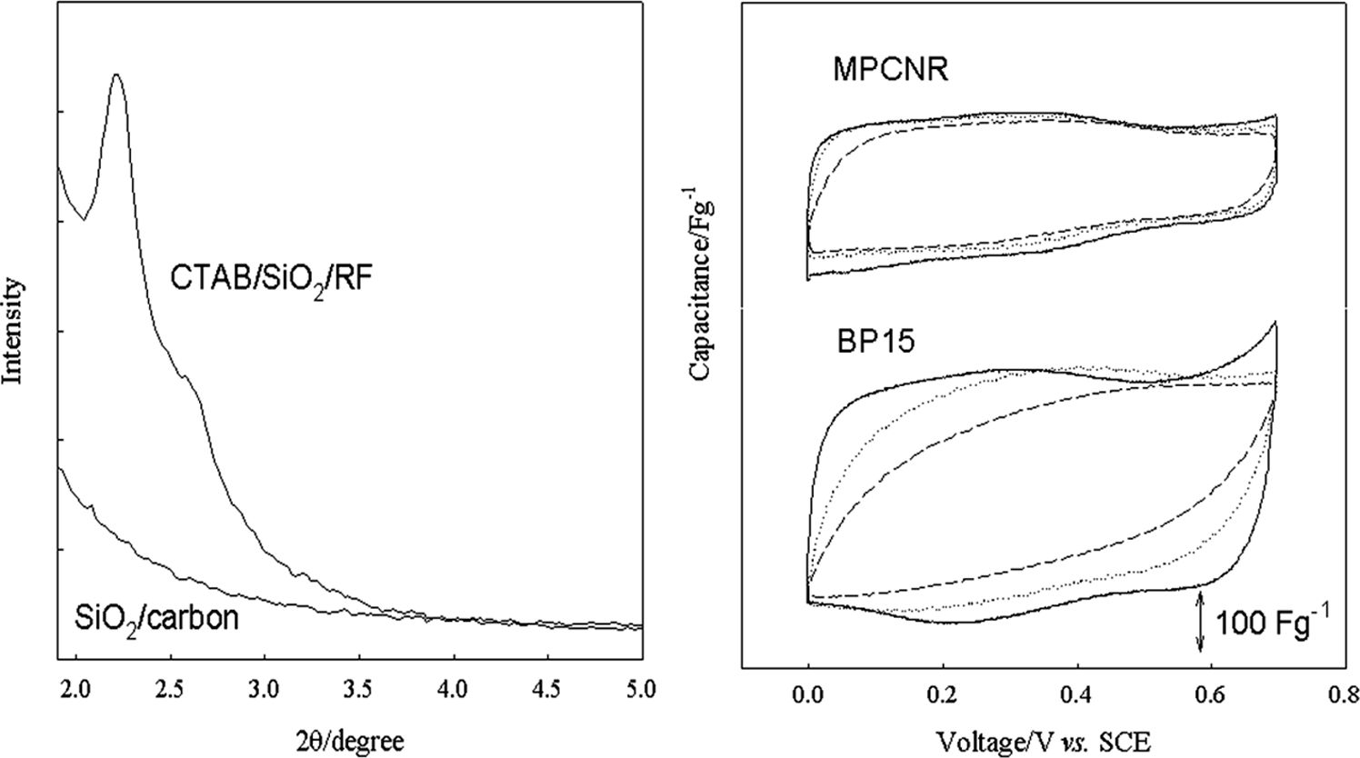
The formation mechanism of MPCNR is provided based on the observation made by Cai et al., who prepared the MCM-41 silica using the same CTAB/silicate.11 According to this, TEOS converts to the multi-charged D4R anions (double four-ring, [Si8O20]8-) in the highly alkaline (pH~14) condition, which further electrostatically interact with surfactant cations to form rod-like self-assembled silicate micelles (SSM). The individual SSM tends to be stacked with hexagonal ordering to form a submicron-sized rod-shaped agglomerate. Cai et al. obtained the submicron-sized rod-shaped porous silica after calcinating this material. In this work, however, the carbon precursor (resorcinol and formaldehyde) was imbibed by the submicron-sized rod-shaped SSM agglomerate that acts as a template, thereby we obtained the carbon nanorod after removing the template.12,13 This synthetic mechanism was also reported in our previous reports.6,7 The carbon nanorods must be generated by the templating action of submicrometer-sized rod-shaped SSM patterns of CTAB/SiO2/RF gel in this work, as shown in Figure 1. As seen, the XRD pattern is very close to that of CTAB/silicate hexagonal tubular mesophase which is the reaction intermediate in the synthesis of hexagonal MCM-41 silica, but less well defined higher order peaks.12,13 When the unit cell parameter (ao) was obtained using the Bragg’s law (λ = 2d100sinq; λ = 0.154 nm) and the formula of ao = 2d100/31/2 for hexagonal unit cell, ao of 4 nm size was obtained that is very close to that of hexagonal tubular mesophase.11,12 It is thus certain that the hexagonal tubular mesophase of CTAB/silicate formed before adding RF and acted as a template for the RF gel. The absence of higher order peaks indicates a lack of long-range ordering or finite size effects. The carbonization of CTAB/SiO2/RF above 600 ℃ results in a loss of ordering as evidenced by the absence of diffraction peaks in the lower pattern in Figure 1(SiO2/carbon). It is likely that, upon carbonization of RF resin, volume contraction is so large as about 50% that the ordered silica domain is collapsed due to mechanical stress.9
Figure 2(a) and 2(b) show the transmission electron microscope (TEM) picture of the SiO2/carbon. Clearly, a rod shape with ca. 100 nm diameter and several hundred nm length appeared. This rod-shaped external morphology was retained after HF acid etching with formation of mesoporous structure in MPCNR as shown in Figure 2(c) and 2(d), where a high population of pores (lighter image) can also be recognized. As seen, well-developed mesoporous structure was observed after HF etching, which was generated by silica components in the SiO2/carbon material. Figure 3 shows the N2 adsorption/desorption profile taken for MPCNR, which has typical type IV isotherm pattern.14 An adsorbed volume was linearly increased at low pressures and following a steeper slope in nitrogen uptake from 0.4 to 0.6 P/P0 were observed. This is attributed to the capillary condensation inside
the mesopores in MPCNR. The pore size distribution that was calculated by Barret, Joyner, and Halenda (BJH) method is presented in the inset. Pores ranging from 1 to 10 nm are dominant with 3.0 nm average pore diameter. This material was named as mesoporous carbon nanorod (MPCNR) based on its pore size and external shape. The BET surface area and pore volume was 620 m2 g-1 and 0.80 cm3 g-1, respectively. Because MPCNR has well-developed mesoporosity and nanosized rod-like shape, it is certain that the charge uptake property as EDLC electrode can be enhanced with fast electrolyte adsorption through mesopores and short migration length within nanorod. Hence MPCNR has a highly optimized porous structure for EDLC electrode due to its characteristic mesoporosity and nanosized rod shape. The EDLC performance of MPCNR was compared to that of BP15 (provided by Kuraray Chemical Co.), which is widely utilized as EDLC electrode materials. BP15 has a surface area of 1450 m2 g-1 and average pore diameter of 2.1 nm.9 Figure 4 shows the potential-dependent capacitance profile of BP15 and MPCNR electrodes. Since BP15 is prepared by conventional activation process, its pore structure has random connectivity when compared with MPCNR. The specific capacitance (Csp) that were estimated at 0.2 V vs. SCE (0.5 mV s-1) in anodic scan is roughly proportional to the surface area. 108 and 185 F g-1 for MPCNR and BP15, respectively. Due to the high ABET of BP15, it has a higher Csp value than MPCNR. As an important performance parameters in EDLC electrode, however, double layer capacitance per area (Cd) is highly recommended in EDLC electrode.15 It has been reported that typical value of Cd is known to have 10~15 µF cm-2 for activated carbon.2,3,14 This value is variable according to heat treatment temperature of carbon, which is estimated by dividing specific capacitance with BET surface area. MPCNR has much higher value of 17.4 µF cm-2 than Cd of BP15, reflecting highly efficient utilization of inner pore surface. This is certainly due to well mesoporosity and high accessibility of pore from nanorod shape carbon particle of MPCNR. According to increase of scan rate from 5 to 50 mV s-1, large collapse of rectangular shape was observed for BP15 in Figure 4. In contrast, shape of MPCNR is almost consistent irrespective of scan rate, which was certainly ascribed to fast electrolyte uptake under high scan rate. This shape change of in capacitance vs. voltage profile under high scan rate was elucidated by the low time constant of EDLC electrode. Since time constant (t) of EDLC electrode was estimated by multiplication between equivalent series resistance (ESR) and capacitance (C); t = ESR × C. When considering low capacitance of MPCNR, it is worthwhile to evaluated ESR value in the MPCNR and BP15 electrodes.
To obtain EDLC with high rate performance, low ESR is indispensable while high capacitance was maintained. In general, ESR can be represented as followings.5,14
Here, Relectrode, Rpore and Rbulk correspond to electronic resistance of electrode, pore resistance and bulk ionic resistance between working and reference electrode, respectively. After adding conducting materials above 7 wt%, Relectrode was so small as about 0.2 mΩ cm2 g. Rbulk was calculated to be 3.0 mΩ cm2 g, which was estimated in our previous report. Above two values of resistance were almost constant for two carbon electrodes.2,5 Value of ESR was measured by chronoamperometry as shown in Figure 5. Here, 10 mV voltage step was applied into two EDLC electrodes at 0.5 V vs. SCE and following current density was recorded in very 10 ms. The inset equation of Figure 5 was used for the calculation of ESR. After extraction of Rbulk and Relectrode from ESR, Rpore was estimated and compared. Rpore values of two carbon electrodes were 3.4 and 15.0 mΩ cm2 g for MPCNR and BP15, respectively. For better comparison, all of calculated data was presented at Table 1. As listed, Rpore of MPCNR has much lower than that of BP15 electrode. Because MPCNR has well developed mesopores within nanorod particles, low Rpore of MPCNR is mostly due to large pores size with short pore length within nanorod.
Galvanostatic charge-discharge was conducted for both electrode under 0.5 and 25 mA cm-2 current density in Figure 6. The effect of pore length on rate capability is demonstrated by providing the charge-discharge voltage profiles of two electrodes (Figure 6), where the downward curves correspond to the charging and the upward ones discharging. BP15 delivers a higher charge-discharge capacity when cycled at the lower current density (0.5 mA cm-2). When cycled at the higher current density (25 mA cm-2), however, MPCNR exhibits a higher capacity than BP15. The higher performance of MPCNR over BP15 at high current condition can be explained by the small voltage drop appeared at the initial transient period of charging and discharging. Especially under 25 mA cm-2, the voltage drop is much larger in the BP15 electrode, thereby the charge-discharge limit is reached earlier, giving a smaller charge-discharge capacity. This high rate capability of MPCNR was certainly due to low ESR value, which was originated from small Rpore value.5,7 Consequently, our MPCNR carbon materials exhibited excellent rate performance in EDLC electrode, when compared with conventional EDLC activated carbon of BP15.

|
Figure 1 Small angle X-ray diffraction patterns of CTAB/SiO2/RF nanocomposite and SiO2/carbon material after carbonization process. |

|
Figure 2 (a) and (b); TEM images for SiO2/carbon nanocomposite before HF etching. (c) and (d); TEM images of MPCNR. |

|
Figure 3 N2 sorption profiles and BJH pore size distribution from adsorption branch of MPCNR. |

|
Figure 4 Capacitance vs. voltage profiles for MPCNR and BP15 electrode which was obtained by dividing specific current by scan rate. Solid, dotted and dashed line are 5, 10, 50 mV s-1 scan rate |

|
Figure 5 Chronoamperometry profiels for MPCNR and BP15 measured at every 10 ms at 0.5 V vs. SCE under 10 mV potential s |

|
Figure 6 Galvanostatic charge-discharge patterns for MPCNR and BP15 electrodes measured at 0.5 and 25 mA cm-2 between voltage range from 0 to 0.7 V vs SCE. |
|
Table 1 Pore Parameters and EDLC Properties of Two Carbon Electrodes |

a The average pore diameter estimated by BJH method. b The surface area estimated from BET method. c The total pore volume at the relative pressure of P/P0 = 0.98 . d The specific capacitance calculated from the cyclic voltammograms taken at 5 mV sec-1 (Figure 4). e Double-layer capacitance per area (Csp/ABET). f Pore resistance estimated from chronomamperometry (Figure 4). |
Using direct templating method, mesoporous nanorod carbon particles were obtained from the self-assembled surfactant/silicate micelles. By polymerization, carbonization and acid etching, well developed mesopores with several hundred nm sized rod particles were clearly observed. When applied into electric double layer capacitor electrode, a highly improved rate performance and a large capacitance per area than conventional activated carbon were observed, which was attributed a better penetration of electrolyte through meospores and optimized pore length.
- 1. Kyotani, T. Control of Pore Structure in Carbon. Carbon 2000, 38, 269-286.
-

- 2. Kötz, R.; Carlen, M. Principles and Applications of Electrochemical Capacitors. Electrochim. Acta 2000, 45, 2483-2498.
-
- 3. Conway, B. E. Electrochemical Supercapacitors-Scientific Fundamentals and Technological Applications; Kluwer Academic/Plenum Publisher: New York, USA, 1999.
- 4. Kinoshita, K.; Chu, X. Proceedings of The Symposium on Electrochemical Capacitors, Delnick, F. M., Tomkiewicz, M., Eds.; The Electrochemical Society, Pennington, 1996, PV 95-29, p. 171.
- 5. Yoon, S.; Lee, J. W.; Hyeon, T.; Oh, S. M. Electric Double-layer Capacitor Performance of a New Mesoporous Carbon. J. Electrochem. Soc. 2000, 147, 2507-2512.
-
- 6. Yoon, S.; Oh, S. M.; Lee, C. Direct Template Synthesis of Mesoporous Carbon and its Application to Supercapacitor Electrodes. Mater. Res. Bull. 2009, 44, 1663-1669.
-
- 7. Yoon, S.; Oh, S. M.; Lee, C. W.; Lee, J.-W. Influence of Particle Size on Rate Performance of Mesoporous Carbon Electric Double-Layer Capacitor (EDLC) Electrodes. J. Electrochem. Soc. 2010, 157, A1229.
-
- 8. Pekala, R. W.; Schaefer, D. W. Structure of Organic Aerogels. 1. Morphology and Scaling. Macromolecules 1993, 26, 5487-5493.
-
- 9. Pekala, R. W. Organic Aerogels from the Polycondensation of Resorcinol with Formaldehyde. J. Mater. Sci. 1989, 24, 3221-3227.
-
- 10. Park, B. W.; Yoon, D. Y.; Park, S. Influence of Processing Temperature on the Image Transfer Characteristics of an Image Guide Made of Polymer Optical Fibers. Korean J. Chem. Eng. 2008, 25, 185-189.
-
- 11. Cai, Q.; Luo, Z.-S.; Pang, W.-Q.; Fan, Y.-W.; Chen, X.-H.; Cui, F.-Z. Dilute Solution Routes to Various Controllable Morphologies of MCM-41 Silica with a Basic Medium. Chem. Mater. 2001, 13, 258-263.
-
- 12. Zhao, D.; Feng, J.; Huo, Q.; Melosh, N.; Fredrickson, H. H.; Chimelka B. F.; Stucky, G. D. Triblock Copolymer Syntheses of Mesoporous Silica with Periodic 50 to 300 Angstrom Pores. Science 1998, 279, 548-552.
-
- 13. Ying, J. Y.; Mehnert, C. P.; Wong, M. S. Synthesis and Applications of Supramolecular-Templated Mesoporous Materials. Angew. Chem. Int. Ed. 1999, 38, 56-77.
-
- 14. Gregg, S. J.; Sing, K. S. W. Adsorption, Surface Area and Porosity; Academic Press: London, 1982.
- 15. Kinoshita, K. Carbon: Electrochemical and Physicochemical Properties; John Wiley & Sons: New York, USA, 1988.
- Polymer(Korea) 폴리머
- Frequency : Bimonthly(odd)
ISSN 0379-153X(Print)
ISSN 2234-8077(Online)
Abbr. Polym. Korea - 2023 Impact Factor : 0.4
- Indexed in SCIE
 This Article
-
2021; 45(3): 450-455
Published online May 25, 2021
- 10.7317/pk.2021.45.3.450
- Received on Feb 2, 2021
- Revised on Feb 8, 2021
- Accepted on Feb 10, 2021
Services
- Full Text PDF
- Abstract
- ToC
- Acknowledgements
Introduction
Experimental
Results and Discussion
Conclusions
- References
Shared
Correspondence to
- Sung Gyu Pyo and Songhun Yoon
-
School of Integrative Engineering, Chung-Ang University, 221, Heukseok-Dong, Dongjak-Gu, Seoul 06974, Korea
- E-mail: sgpyo@cau.ac.kr, yoonshun@cau.ac.kr
- ORCID:
000-0002-0962-7470
Hyecheon Building(Room 601), #354, Gangnam-Daero, Gangnam-Gu, Seoul 06242, Korea
TEL : 82-2-568-3860, 561-5203, 569-3860 FAX : 82-2553-6938 E-mail: polymer@polymer.or.kr