


- Controlling Internal Pore Structure of Porous Carbon Nanofibers Based on the Miscibility between Polyacrylonitrile Matrix and Sacrificial Polymers
Hyunmin Hwang*, Dong Wook Chae**, and Youngho Eom†

Department of Polymer Engineering, Pukyong National University, Busan 48513, Korea
*LG Household & Health Care, Seoul 07785, Korea
**Department of Textile Engineering, Kyungpook National University, Sangju 37224, Korea- 폴리아크릴로니트릴과 희생용 고분자 간 혼화성을 기반으로 한 다공성 탄소나노섬유의 내부기공구조 제어
황현민* · 채동욱** · 엄영호†
부경대학교 고분자공학과, *LG생활건강, **경북대학교 섬유공학과
Reproduction, stored in a retrieval system, or transmitted in any form of any part of this publication is permitted only by written permission from the Polymer Society of Korea.
Porous carbon nanofibers were prepared via electrospinning of polyacrylonitrile (PAN)-based blend solutions and effects of miscibility of the blended polymers on pore structure were investigated. Two sacrificial polymers, poly(vinylidene fluoride) (PVDF) and poly(styrene-co-acrylonitrile) (SAN), were chosen as a sacrificial component to yield porosity after carbonization. The miscibility of PAN with each sacrificial polymer was evaluated both theoretically and empirically. Analyzing solubility parameters revealed that PVDF had higher chemical affinity with PAN due to dipole-dipole interaction than SAN. Lower value of Flory-Huggins interaction parameter of PAN with PVDF (0.52) than with SAN (1.19) quantitatively confirmed the better miscibility of PAN-PVDF. In dynamic mechanical analysis of PAN/PVDF blend films, individual loss tangent (tan d) peaks (i.e., glass transition peak) for PAN and PVDF were observed but they were shifted to each other, indicating partial miscibility. In PAN/SAN films, however, the peak shift of PAN was negligible. These results coincided well with the theoretical analysis. After carbonization, the blend nanofibers exhibited high porosity with different pore structures; elongated shape for PVDF and round shape for SAN system. The pore structure discrepancy in the two systems was ascribed to the miscibility difference of each sacrificial polymer with PAN matrix.
폴리아크릴로니트릴(PAN) 기반 혼합 용액의 전기방사를 통해 다공성 탄소나노섬유를 제조하였으며, 혼합된 고분자와 PAN 간 혼화성이 기공 구조에 미치는 영향이 연구되었다. 탄화 후 다공성을 부여하기 위해 희생용 고분자로 폴리비닐리덴플로우라이드(PVDF)와 스티렌-아크릴로니트릴 공중합체(SAN) 두 종이 선택되었고, PAN과 두 희생용 고분자 간 혼화성은 이론 및 실험적으로 평가되었다. 용해도 지수 분석 결과 SAN보다 PVDF가 쌍극자-쌍극자 상호작용을 통해 PAN과 더 가까운 친화성을 가짐이 증명되었다. PAN과 SAN(1.19)보다 PVDF(0.52) 간 더 낮은 용해도 지수 값은 PAN-PVDF계의 더 우수한 혼화성을 정량적으로 뒷받침해주었다. PAN/PVDF 혼합 필름의 동적 기계 분석에서, PAN과 PVDF의 유리전이온도를 나타내는 손실 탄젠트(tan d) 피크가 각각 관찰되었고 서로를 향하여 이동하는 현상은 두 고분자의 부분적 혼화성을 입증하였다. 하지만, PAN/SAN 혼합필름의 경우, PAN의 tan d 피크 이동이 미미하였고, 이는 낮은 혼화성을 나타내는 이론적 분석 결과와 일치하였다. 탄화 후 PVDF계 혼합섬유는 길쭉한 형태의 기공구조를 보이는 반면, SAN계는 원형 기공구조를 가졌다. 이러한 기공구조의 차이는 두 희생용 고분자와 PAN 간의 혼화성 차이에 기인하였다
Electrospun carbon nanofibers were prepared using polyacylonitrile (PAN)-based blend solutions and effects of miscibility of the blended polymers on pore structure was investigated. Poly(vinylidene fluoride) (PVDF) and poly(styrene-co-acrylonitrile) (SAN) were chosen as a sacrificial component. The carbonized blend fibers exhibited different pore structures due to miscibility difference with PAN; elongated shape for PVDF and round shape for SAN system.
Keywords: polyacrylonitrile, porous carbon nanofibers, electrospinning, solubility parameter, Flory-Huggins interaction parameter.
This research was supported by the National Research Foundation of Korea (NRF-2020R1C1C 1009340) and the Korea Institute of Energy Technology Evaluation and Planning (KETEP) and the Ministry of Trade, Industry & Energy (MOTIE) of the Republic of Korea (No. 20194010201840).
Porous carbon nanofiber is widely used in the fields of gas storage, separation and purification, catalyst carriers, and electrode materials due to its unique mechanical and thermal
properties, chemical inertness and high specific surface area.1-8 Its high specific surface area, one of the most distinguishing features of porous carbon nanofiber, is spotlighted mostly in the fields of adsorbent and electrochemical fields such as anode material for lithium ion batteries and cathode material for supercapacitor. The desired pore structure depends on its application. In the fields of adsorbent, El-Merraoui et al.9 suggested that the adsorbed amount is mainly dependent on particularly the structure of micropores. Lee et al.10 reported that the shallow micropores are advantageous in adsorbing formaldehyde. On the other hand, mesopores are desirable in the applications of lithium-ion batteries and supercapacitors due to trapping of the micropores.11
Several methods to prepare porous carbon nanofiber and to control the pore structure have been studied by many researchers. Generally used method is activation.12-14 However, the activation method has some drawbacks such as requirement for additional equipment set up and extra step when post-treated after carbonization. Thus, other methods that create pores directly during carbonization are also being explored. Wang et al.15 controlled the heating rate of stabilization and carbonization steps to prepare porous carbon nanofiber. The specific surface area of the resulting carbon nanofibers increased at higher heating rates. Other researchers blended inorganic materials into PAN solution as a sacrificial material.16,17
One of the most outstanding ways to drastically increase the specific surface area is to prepare the fiber with a polymer blend solution. The precursor polymer is blended with a sacrificial polymer which can be eliminated by pyrolysis or solvent extraction. The sacrificial polymer leaves pore throughout the fibers and increases the specific surface area after proper treatment. Tran et al.18 blended PAN with Nafion, where Nafion was used as a sacrificial polymer. The resultant porous carbon nanofibers exhibited specific surface area up to 1600 m2/g with a large fraction of mesopores, while that of the fibers spun from pristine PAN solution exhibited 339 m2/g. Other researchers used poly(acrylonitrile-co-methyl methacrylate) or poly(styrene-co-acrylonitrile) (SAN) as a sacrificial polymer.2,7 In the study by Zhang et al.,19 as-spun PAN fibers blended respectively with poly(ethylene oxide), cellulose acetate and poly (methyl methacrylate) were treated with solvent for the extraction of the sacrificial part prior to heat treatment. These methods are available not only for the PAN-based fibers but also the fibers based on other polymers.4
There have been many attempts to increase the specific surface area by spinning the polymer blend solution dope, but the resulting pore structure of the fibers was not discussed in terms of the polymer miscibility. Since the pore structure of the carbonized fiber is affected by the phase separation behavior of the precursor fiber, the polymer miscibility can be a useful parameter to predict and analyze the pore structure of the fiber. In this study, PAN-based blend solutions were electrospun to fabricate precursors for carbon nanofiber. PAN was blended with poly(vinylidene fluoride) (PVDF) and SAN, respectively. PAN is a widely used precursor which shows high carbon yield after carbonization. PVDF and SAN, on the other hand, decompose during heat treatment. The resultant carbon nanofibers were discussed in terms of solution miscibility and the morphology of the fibers.
Materials.PAN (Mw ~ 150000), PVDF (Mw ~ 275000) and SAN (Mw ~ 165000; AN content of 25 wt%) were purchased from Sigma Aldrich (USA). N,N-dimethyl formamide (DMF), purchased from Duksan (Korea), was used as a common solvent.
Solution Preparation and Electrospinning.The blend solutions were prepared by dissolving PAN and sacrificial component in DMF. The mixture was stirred at 60 °C for 6 h. The solution concentrations were fixed to 12 wt% and each blend was prepared in the ratio of 95:5, 90:10, 85:15 and 80:20 for PAN:PVDF or SAN. The solutions were coded as PAN/XY where X and Y are the sacrificial polymer and its weight fraction, respectively.
The blended solutions were then poured into the syringe. The solutions were pushed out through a needle with diameter of 0.5 mm at a flow rate of 3 mL/h. The fibers were collected on rotating drum under 17 kV while tip-to-collector distance was fixed at 15 cm.
Characterization of the Blend Solutions.Prepared solutions were optically analyzed with an optical microscope (Olympus BX51, Olympus, Japan) to ensure that the solution is stable during electrospinning process. A droplet of as-dissolved solution was taken on the slide glass. The droplet was observed at magnification of 50x. The diameter of the spherical domains of the sacrificial polymers was measured and average of 200 values was used as the representative value of each blend solution. Standard deviations of the diameters were also calculated. Same procedure was conducted after keeping the solution at room temperature for 4 h to evaluate the phase stability.
The solutions were casted in films for dynamic mechanical analysis (DMA) to measure the glass transition temperature (Tg) using Q800 (TA instruments, USA). The films were casted on the glass plate and dried at 60 °C for 48 h. The casted films were cut in size of 4 cm by 1 cm for the DMA measurement. The frequency and heating rate were 1 Hz and 5 °C/min, respectively.
Carbonization of the Electrospun Nanofibers. The as-spun fibers were stabilized under air atmosphere prior to carbonization. The flow rate of air and the heating rate were 200 cc/min and 1 °C/min, respectively. The fibers were held at 230 °C for 1 h and at 270 °C for 30 min. The stabilized fiber mats were then treated at 800 °C for 1 h at the heating rate of 5 °C/min for carbonization. The carbonization step was performed under N2 atmosphere with a flow rate of 200 cc/min.
Characterization of the As-spun and Carbonized Fibers.The surface morphology of the as-spun and heat-treated fibers was observed by field emission scanning electron microscopy (FE-SEM, JSM-6340F, JEOL, Japan). The as-spun and stabilized fibers were sputter-coated with Pt for 3 min prior to observation to enhance conductivity to the samples. The carbonized fibers were observed without any post-treatments.
The inner-pore and its morphology of the carbonized fibers were observed by transmission electron microscope (TEM, JEM-2100F, JEOL, Japan). The carbonized fibers were dispersed in ethanol by sonication for 5 min. The droplets of the fiber-containing solution were dropped on the grid and dried in a conventional oven for a day at 60 °C.
The nitrogen gas adsorption-desorption isotherms of the carbon nanofibers were measured using an automatic gas adsorption apparatus (ASAP 2000, Micromeritics, USA). Brunauer-Emmett-Teller (BET) specific surface areas were calculated from the adsorption isotherms.
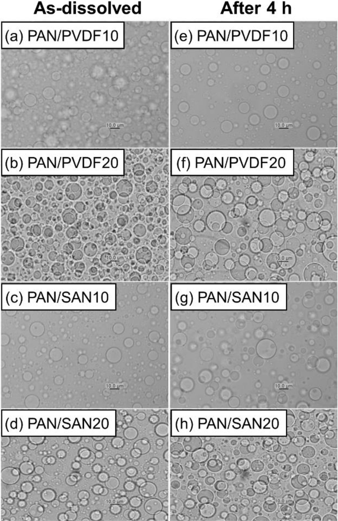
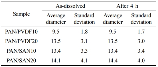
Miscibility of the Blend Solutions.In order to impart the high porosity and eventually control the pore structure of the final PAN-based carbon fibers, two blend polymers having different miscibility with PAN, PVDF and SAN, were chosen as the sacrificial component during carbonization. Figure 1 shows the blend morphology of PAN/PVDF and PAN/SAN solutions at the blend ratios of 90:10 and 80:20, respectively. Both PVDF and SAN produce the domain structure in PAN/DMF solutions, indicating poor miscibility. The domain size of the sacrificial component determines the pore structure and resultant porosity of the PAN-based carbon nanofibers. The average diameter and standard deviation of the sacrificial polymer domains are optically measured and summarized in Table 1. At the blend ratio of 80:20, PAN/PVDF and PAN/SAN solutions give the diameter of 13.5±3.1 and 14.15±4.1 μm, respectively. Although the incorporation of the poorly miscible polymers is an effective way to afford the porosity in the resultant fiber, they are able to degrade the phase stability and related solution spinnability in the electrospinning process. Fortunately, the blend solutions exhibit similar phase morphology even after 4 h and the domain sizes of the sacrificial polymers remain almost constant. That is, it can be conjectured that the sacrificial polymers, PVDF and SAN, are limitedly miscible or compatible with PAN.
The miscibility of the polymeric components was theoretically evaluated using the solubility parameter. The overall and individual solubility parameters (Hansen solubility parameter) of each material are listed in Table 2. The solubility parameters for PAN and PVDF were calculated based on the Van Krevelen group contribution method,20 while that of the copolymer, SAN, was calculated according to the equation suggested by B. Schneier.21 As a rule, the closer solubility parameter values of two components indicate their stronger chemical affinity.22 Comparing the two sacrificial polymers, PVDF gives a lower value difference in the overall solubility parameter with PAN (4.2) than SAN (6.2), suggesting the better affinity of PAN-PVDF. Meanwhile, the previous study reported that the chemical affinity of highly polar PAN is dominantly governed by the polar term (δp) instead of the overall δ. The higher chemical affinity of PAN-PVDF than PAN-SAN can be further proven in the δp. The δp difference of PAN-PVDF (2.0) is much lower than that of PAN-SAN (8.0). In other words, PAN and PVDF are partially miscible due to the dipole-dipole interaction.
The interaction parameter calculated from the solubility parameters offers quantitative information on the miscibility of polymer-polymer system.23,24 The equation for interaction parameter is expressed as
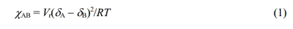
where R, T, Vr, δA and δB represent ideal gas constant, absolute temperature and molar volume of the solvent, solubility parameters of substance A and B, respectively. The polymer-polymer system tends to be more miscible when the interaction parameter is closer to 0. In the case of the PAN-based blends, the χPAN-PVDF and χPAN-SAN are 0.52 and 1.19 at room temperature, respectively. This result further confirms the higher miscibility of PAN with PVDF than SAN.
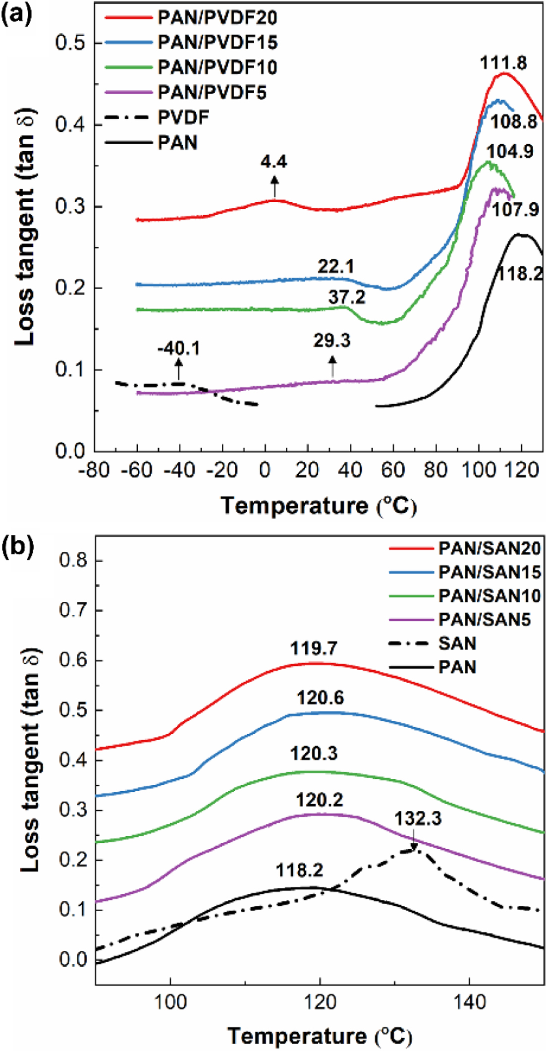
The determination of Tg is widely used to experimentally investigate the miscibility of the polymeric blend. In a completely miscible blend system, it would show a single Tg in the middle of the individual Tgs of each polymer due to a co-operative motion of the polymer chains, while partially miscible or immiscible blend exhibits double Tgs from each component. However, the Tg peaks tend to shift to each other in a partially miscible system. Figure 2 shows the loss tangent (tan d) DMA curves of the PAN/PVDF and PAN/SAN blend films and their Tg peaks are denoted.
In PAN/PVDF blend systems (Figure 2(a)), the neat PAN and PVDF specimens give Tg at 118.2 and -40.1 °C, respectively, and their shifts to each other are obviously observed in the blend films. The peak shift is direct evidence of the interactive segmental motion of blended polymers. Particularly, PAN/PVDF10 film shows the strongest shift among the blend ratios; Tg of PAN at 104.9 °C (from 118.2 °C) and that of PVDF at 22.1 °C (from -40.1 °C).
This result strongly verifies the partial miscibility of PAN-PVDF, which coincides well with the theoretical evaluation by the solubility parameters. Zhong et al.25 reported that PVDF and PAN are capable of forming polar and hydrogen bonding. Unfortunately, at the high blend ratios of 15 and 20 wt% PVDF, the degree of the peak shift (i.e., miscibility) decreases drastically, agreeing with some previous reports.26,27
In PAN/SAN blend systems (Figure 2(b)), the Tg peak for SAN was hardly observed because Tgs of neat PAN (118.2 °C) and SAN (132.3 °C) are close to each other, and as a result, the Tg of SAN is overlapped with that of PAN. Hence, the miscibility of PAN/SAN blend was judged by the shift in Tg peak of PAN. Contrary to the PAN/PVDF blends, the Tg of PAN in PAN/SAN blend films exhibits negligible peak shift. This confirms the low miscibility of PAN-SAN. Even that SAN has nitrile groups within the structure, only 40 mol% of them exist in SAN. The limited amount of the interaction sites is also hindered by the bulky styrene groups. The miscibility behavior investigated by DMA also correlates with the result predicted by the theoretical interaction parameters.
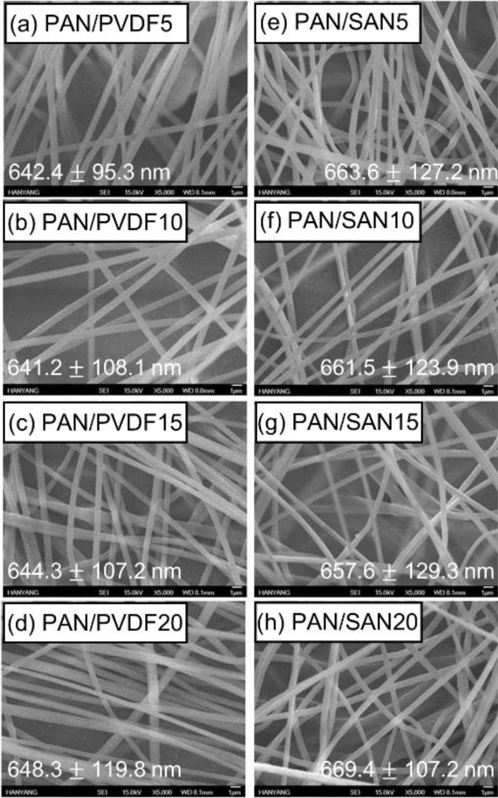
Morphology of As-Spun and Heat-Treated Fibers.Figure 3 exhibits SEM images of the as-spun blend nanofibers. The adding of the sacrificial polymers has an insignificant effect on the surface morphology and diameter of the electrospun PAN nanofibers, and as a result, the fiber diameters of all the samples are in the range of from 641.2±108.1 to 669.4±107.2 nm. According to previous researches, the blend nanofibers exhibited thinner diameter at a higher amount of the sacrificial polymer due to the low molecular weight of the additive component such as cellulose acetate.28,29 In this case, however, the diameter difference of the PAN-based blend fibers is within the range of 10%. This insignificant diameter variation is ascribed to the high Mw of PVDF (275000) and SAN (16500) comparable to that of the matrix PAN (150000).
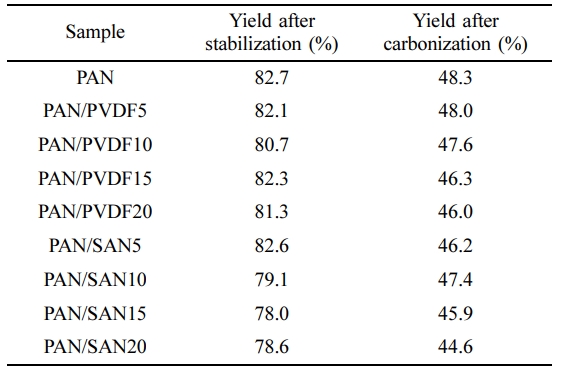
In the preparation of the carbon nanofibers, the oxidative stabilization process is an essential stage prior to the carbonization to increase the carbon yield of the PAN fiber. This step includes cyclization of the linear structure which leads to formation of more stable ladder structure.30 The ladder structured PAN fiber can endure in high carbonization temperature without being decomposed. The diameter of the fibers decreases due to the structural change, along with the weight loss caused by the dehydrogenation. The weight yield of the stabilized and carbonized PAN-based nanofibers is summarized in Table 3. The final carbon yield of the neat PAN and blended nanofibers is in the range of 40-50%.
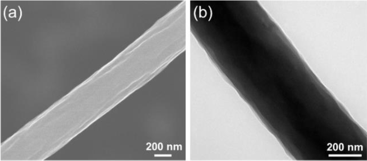
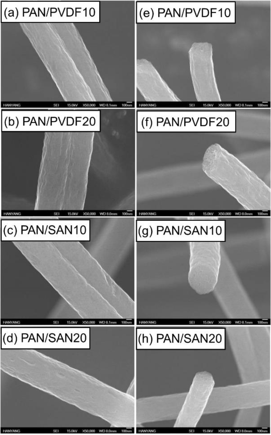
The SEM and TEM images were taken to observe the surface and internal morphologies of the carbonized fibers. Compared to the surface SEM image of pristine PAN carbon nanofiber (Figure 4(a)), the carbonized blend nanofibers exhibit rough and uneven surfaces owing to the removal of the sacrificial components during the heat-treatment (Figure 5). In particular, the numerous internal pores are observed in the cross-section SEM images of the carbonized blend nanofibers.
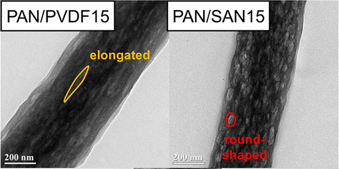
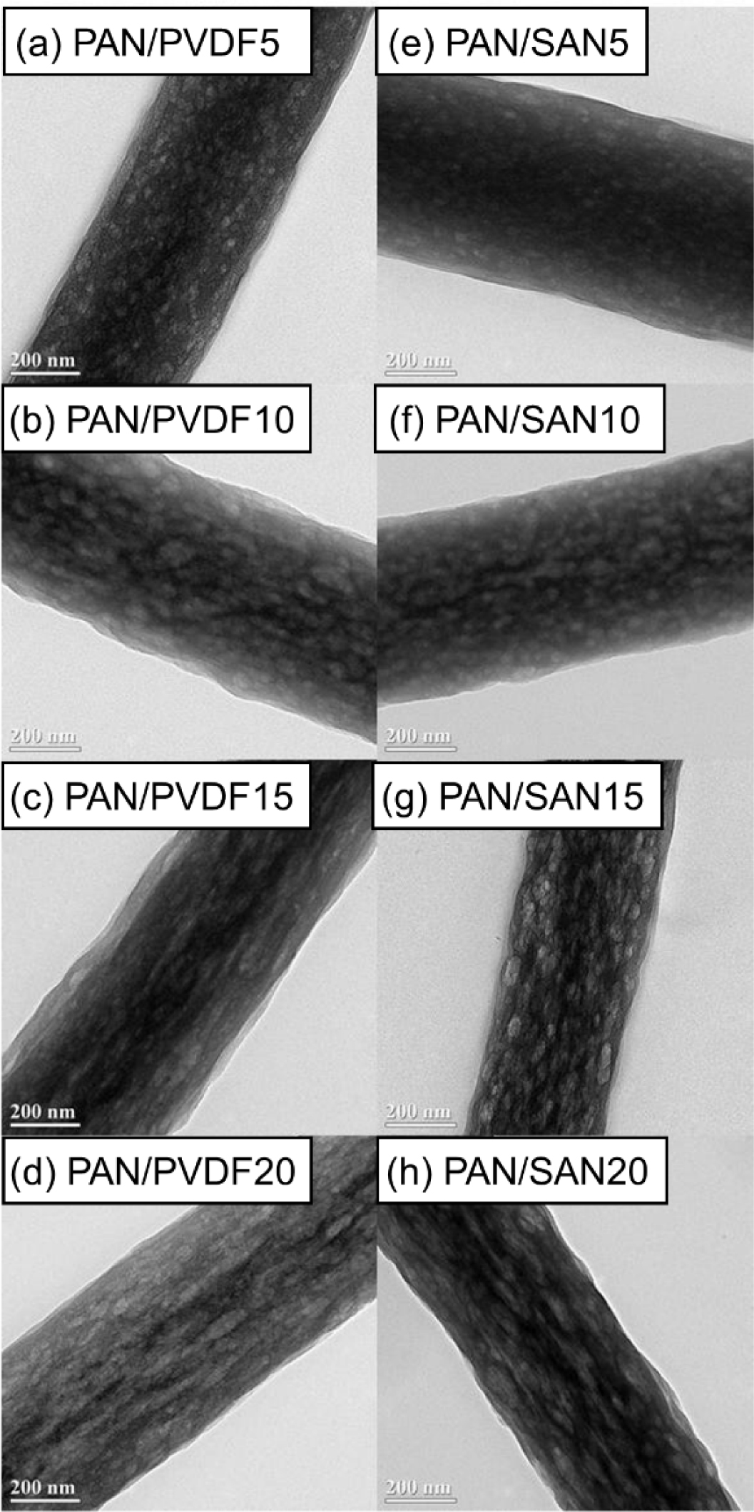
The internal structure of the carbonized nanofibers can be more clearly compared by observing the TEM images. As shown in Figure 4(b), the carbonized neat PAN fiber has non-porous structure. On the other hand, the PAN/PVDF and PAN/SAN blend nanofibers produce a highly porous structure after the carbonization (Figure 6). Interestingly, the two blend systems exhibit different shapes of internal pores. At the blend ratios of 85:15 and 80:20, the elongated internal pores were developed in the PAN/PVDF blend fibers, whereas the pores in the PAN/SAN blend fibers are round- or oval-shaped. The discrepancy of the internal pore structures between the two blend fibers has a strong correlation with the miscibility difference of the sacrificial polymers with PAN. In the fiber forming process during electrospinning, the PAN matrix is extremely stretched with a rapid solvent evaporation. Then, if the incorporated component is well dispersed and mixed with PAN matrix through the high chemical affinity, it will be also stretched during the fiber formation along with the matrix elongation. In this regard, the elongated pore structure of the carbonized PAN/PVDF blend fibers results from their partial miscibility. On the other hand, the poor chemical affinity of PAN and SAN leads to the less-elongated structure of the internal pore.
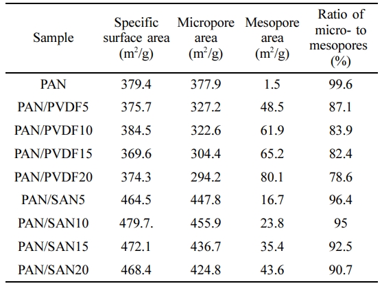
BET Analysis of the Carbonized Nanofibers.The specific surface area of the carbonized fibers was analyzed by BET theory. The results are listed in Table 4 along with the areal fractions of micropore (< 2 nm) and mesopore (2-50 nm). The carbonized neat PAN nanofibers give the specific surface area of 379.4 m2/g consisting of 99.6% micropores due to the release of volatile gases such as H2, HCN, N2, NH3 and CO2 during heat treatment.
In the case of the PAN/PVDF blend systems, the specific surface area is almost unchanged but the fraction of the mesopores is significantly increased. The ratio of micro- to mesopores is sharply reduced by incorporating the 5 wt% PVDF from 99.6% to 87.1%, and then decreases gradually to 78.6% at 20 wt% PVDF. This result reveals that the elongated internal pores are acted as the mesopores. In case of the PAN/SAN blend systems, however, the specific surface area is noticeably increased compared to the neat carbon nanofibers. The increased surface area results from the increased areal fraction of the micropores. Consequently, the round- or oval-shaped pores contribute significantly to the evolution of the micropores.
|
Figure 1 The optical microscopic images of as-dissolved (a) PAN/ PVDF10; (b) PAN/PVDF20; (c) PAN/SAN10; (d) PAN/SAN20 at the magnification of 50x. Images after 4 h are presented in (e~h). |
|
Figure 2 Loss tangent (tan δ) curves of (a) PAN/PVDF; (b) PAN/ SAN blend films in the variation of the blend ratio. The glass transition (Tg) temperatures of each curve were indicated in the figure numerically. |
|
Figure 3 SEM images of as-spun (a) PAN/PVDF5; (b) PAN/ PVDF10; (c) PAN/PVDF15; (d) PAN/PVDF20; (e)PAN/SAN5; (f) PAN/SAN10; (g) PAN/SAN15; (h) PAN/SAN20 nanofibers. |
|
Figure 4 (a) SEM; (b) TEM images of the carbonized pristine PAN nanofiber. |
|
Figure 5 SEM images of the carbonized (a, e) PAN/PVDF10; (b, f) PAN/PVDF20; (c, g) PAN/SAN10; (d, h) PAN/SAN20 nanofibers. The cross-sections are presented in (e~h). |
|
Figure 6 TEM images of the carbonized (a) PAN/PVDF5; (b) PAN/PVDF10; (c) PAN/PVDF15; (d) PAN/PVDF20; (e) PAN/ SAN5; (f) PAN/SAN10; (g) PAN/SAN15; (h) PAN/SAN20 nanofibers. |
|
Table 1 Average Diameter and Standard Deviation of the Sacrificial Polymer Domains at an As-dissolved State and after 4 h (unit: µm) |
|
Table 2 Overall and Individual Solubility Parameters of PAN, PVDF, SAN and DMF |
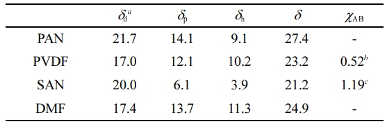
aUnits are in MPa1/2. b χPAN-PVDF. c χPAN-SAN |
The pore structure of PAN-based carbon nanofibers blended with PVDF and SAN, respectively, was analyzed in terms of miscibility between polymers in the blend solutions. The miscibility of PAN matrix and the sacrificial polymer was investigated by several theoretical and experimental methods. The results showed that PVDF was partially miscible with PAN while SAN was almost immiscible. PAN/PVDF blended carbon nanofibers had elongated pore structures while oval-shaped pores were dominant in PAN/SAN blended carbon nanofibers. It was because the partially miscible PVDF domains were also stretched during the fiber formation process of the PAN matrix.
- 1. Miyawaki, J.; Shimohara, T.; Shirahama, N.; Yasutake, A.; Yoshikawa, M.; Mochida, I.; Yoon, S.-H. Removal of NOx from Air through Cooperation of the TiO2 Photocatalyst and Urea on Activated Carbon Fiber at Room Temperature. Appl. Catal. B-Environ. 2011, 110, 273-278.
-

- 2. Peng, M.; Li, D.; Shen, L.; Chen, Y.; Zheng, Q.; Wang, H. Nanoporous Structured Submicrometer Carbon Fibers Prepared via Solution Electrospinning of Polymer Blends. Langmuir 2006, 22, 9368-9374.
-
- 3. Yamashita, J.; Shioya, M.; Kikutani, T.; Hashimoto, T. Activated Carbon Fibers and Films Derived from Poly(vinylidene Fluoride). Carbon 2001, 39, 207-214.
-
- 4. Yang, Y.; Centrone, A.; Chen, L.; Simeon, F.; Hatton, T. A.; Rutledge, G. C. Highly Porous Electrospun Polyvinylidene Fluoride (PVDF)-Based Carbon Fiber. Carbon 2011, 49, 3395-3403.
-
- 5. Jang, J.; Bae, J. Carbon Nanofiber/Polypyrrole Nanocable as Toxic Gas Sensor. Sensor Actuat. B-Chem. 2007, 122, 7-13.
-
- 6. Li, L.; Li, J.; Lukehart, C. M. Graphitic Carbon Nanofiber-Poly(Acrylate) Polymer Brushes as Gas Sensors. Sensor Actuat. B-Chem. 2008, 130, 783-788.
-
- 7. Lee, B.-S.; Son, S.-B.; Park, K.-M.; Seo, J.-H.; Lee, S.-H.; Choi, I.-S.; Oh, K.-H.; Yu, W.-R. Fabrication of Si Core/C Shell Nanofibers and Their Electrochemical Performances as a Lithium-Ion Battery Anode. J. Power Sources 2012, 206, 267-273.
-
- 8. Ji, L.; Lin, Z.; Medford, A. J.; Zhang, X. Porous Carbon Nanofibers from Electrospun Polyacrylonitrile/SiO2 Composites as an Energy Storage Material. Carbon 2009, 47, 3346-3354.
-
- 9. El-Merraoui, M.; Aoshima, M.; Kaneko, K. Micropore Size Distribution of Activated Carbon Fiber Using the Density Functional Theory and Other Methods. Langmuir 2000, 16, 4300-4304.
-
- 10. Lee, K. J.; Shiratori, N.; Lee, G. H.; Miyawaki, J.; Mochida, I.; Yoon, S.-H.; Jang, J. Activated Carbon Nanofiber Produced from Electrospun Polyacrylonitrile Nanofiber as a Highly Efficient Formaldehyde Adsorbent. Carbon 2010, 48, 4248-4255.
-
- 11. Inagaki, M.; Konno, H.; Tanaike, O. Carbon Materials for Electrochemical Capacitors. J. Power Sources 2010, 195, 7880-7903.
-
- 12. Yoon, S.-H.; Lim, S.; Song, Y.; Ota, Y.; Qiao, W.; Tanaka, A.; Mochida, I. KOH Activation of Carbon Nanofibers. Carbon 2004, 42, 1723-1729.
-
- 13. Villar-Rodil, S.; Suarez-Garcia, F.; Paredes, J.; Martinez-Alonso, A.; Tascon, J. Activated Carbon Materials of Uniform Porosity from Polyaramid Fibers. Chem. Mater. 2005, 17, 5893-5908.
-
- 14. Im, J. S.; Park, S.-J.; Kim, T. J.; Kim, Y. H.; Lee, Y.-S. The Study of Controlling Pore Size on Electrospun Carbon Nanofibers for Hydrogen Adsorption. J. Colloid Interface Sci. 2008, 318, 42-49.
-
- 15. Wang, P.; Zhang, D.; Ma, F.; Ou, Y.; Chen, Q. N.; Xie, S.; Li, J. Mesoporous Carbon Nanofibers with a High Surface Area Electrospun from Thermoplastic Polyvinylpyrrolidone. Nanoscale 2012, 4, 7199-7204.
-
- 16. Kim, B.-H.; Yang, K. S. Enhanced Electrical Capacitance of Porous Carbon Nanofibers Derived from Polyacrylonitrile and Boron Trioxide. Electrochim. Acta 2013, 88, 597-603.
-
- 17. Kim, S. Y.; Kim, B.-H.; Yang, K. S.; Oshida, K. Supercapacitive Properties of Porous Carbon Nanofibers via the Electrospinning of Metal Alkoxide-Graphene in Polyacrylonitrile. Mater. Lett. 2012, 87, 157-161.
-
- 18. Tran, C.; Kalra, V. Fabrication of Porous Carbon Nanofibers with Adjustable Pore Sizes as Electrodes for Supercapacitors. J. Power Sources 2013, 235, 289-296.
-
- 19. Zhang, L.; Hsieh, Y.-L. Carbon Nanofibers with Nanoporosity and Hollow Channels from Binary Polyacrylonitrile Systems. Eur. Polym. J. 2009, 45, 47-56.
-
- 20. Park, S.-A.; Eom, Y.; Jeon, H.; Koo, J. M.; Lee, E. S.; Jegal, J.; Hwang, S. Y.; Oh, D. X.; Park, J. Preparation of Synergistically Reinforced Transparent Bio-Polycarbonate Nanocomposites with Highly Dispersed Cellulose Nanocrystals. Green Chem. 2019, 21, 5212-5221.
-
- 21. Schneier, B. An Equation for Calculating the Solubility Parameter of Random Copolymers. J. Polym. SCi. Pol. Lett. 1972, 10, 245-251.
-
- 22. Eom, Y.; Ju, H.; Park, Y.; Chae, D. W.; Jung, Y. M.; Kim, B. C.; Chae, H. G. Effect of Dissolution Pathways of Polyacrylonitrile on the Solution Homogeneity: Thermodynamic- or Kinetic-Controlled Dissolution. Polymer 2020, 205, 122697.
-
- 23. Coleman, M. M.; Serman, C. J.; Bhagwagar, D. E.; Painter, P. C. A Practical Guide to Polymer Miscibility. Polymer 1990, 31, 1187-1203.
-
- 24. David, D.; Sincock, T. Estimation of Miscibility of Polymer Blends Using the Solubility Parameter Concept. Polymer 1992, 33, 4505-4514.
-
- 25. Zhong, G.; Zhang, L.; Su, R.; Wang, K.; Fong, H.; Zhu, L. Understanding Polymorphism Formation in Electrospun Fibers of Immiscible Poly(vinylidene fluoride) Blends. Polymer 2011, 52, 2228-2237.
-
- 26. Liu, T. Y.; Lin, W. C.; Huang, L. Y.; Chen, S. Y.; Yang, M. C. Surface Characteristics and Hemocompatibility of PAN/PVDF Blend Membranes. Polym. Adv. Technol. 2005, 16, 413-419.
-
- 27. Xiuli, Y.; Hongbin, C.; Xiu, W.; Yongxin, Y. Morphology and Properties of Hollow-Fiber Membrane Made by PAN Mixing with Small Amount of PVDF. J. Membr. Sci. 1998, 146, 179-184.
-
- 28. Zhou, W.; He, J.; Cui, S.; Gao, W. Preparation of Electrospun Silk Fibroin/Cellulose Acetate Blend Nanofibers and Their Applications to Heavy Metal Ions Adsorption. Fibers Polym. 2011, 12, 431-437.
-
- 29. Zhijiang, C.; Yi, X.; Haizheng, Y.; Jia, J.; Liu, Y. Poly (Hydroxybutyrate)/Cellulose Acetate Blend Nanofiber Scaffolds: Preparation, Characterization and Cytocompatibility. Mater. Sci. Eng. C 2016, 58, 757-767.
-
- 30. Duan, Q.; Wang, B.; Wang, H. Effects of Stabilization Temperature on Structures and Properties of Polyacrylonitrile (PAN)-Based Stabilized Electrospun Nanofiber Mats. J. Macromol. Sci. B 2012, 51, 2428-2437.
-
- Polymer(Korea) 폴리머
- Frequency : Bimonthly(odd)
ISSN 0379-153X(Print)
ISSN 2234-8077(Online)
Abbr. Polym. Korea - 2023 Impact Factor : 0.4
- Indexed in SCIE
 This Article
-
2021; 45(2): 228-235
Published online Mar 25, 2021
- 10.7317/pk.2021.45.2.228
- Received on Oct 5, 2020
- Revised on Dec 1, 2020
- Accepted on Dec 10, 2020
Services
- Full Text PDF
- Abstract
- ToC
- Acknowledgements
Introduction
Experimental
Results and Discussion
Conclusions
- References
Shared
Correspondence to
- Youngho Eom
-
Department of Polymer Engineering, Pukyong National University, Busan 48513, Korea
- E-mail: eomyh@pknu.ac.kr
- ORCID:
0000-0002-0922-1155
Hyecheon Building(Room 601), #354, Gangnam-Daero, Gangnam-Gu, Seoul 06242, Korea
TEL : 82-2-568-3860, 561-5203, 569-3860 FAX : 82-2553-6938 E-mail: polymer@polymer.or.kr