


- Effect of Maleic Anhydride-grafted Polypropylene on Recycled Carbon Fiber Reinforced Polypropylene
SeungJae Ahn, Yu Yan, and Han-Yong Jeon*,†

Department of Chemistry and Chemical Engineering, Inha University, 100 Inha-ro, Michuhol-gu, Incheon 22212, Korea
*Department of Chemical Engineering, Inha University, 100 Inha-ro, Michuhol-gu, Incheon 22212, Korea- 말레산 무수물 그래프트 폴리프로필렌이 재생 탄소섬유 보강 폴리프로필렌에 미치는 영향
안승재 · 연 우 · 전한용*,†
인하대학교 대학원 화학화공융합과, *인하대학교 화학공학과
As the problem of plastic
based material waste is increasing, carbon fiber reinforced plastics (CFRPs)
need to achieve closed life cycle. This study aims to investigate the potential
for recycled carbon fiber reinforced plastics (rCFRPs) with polypropylene (PP).
To improve mechanical properties of rCFRP, maleic anhydride grafted
polypropylene (MAPP) was used as a coupling agent due to absence of functional
group in PP. The rCFRPs were prepared by compression molding after stacking of
recycled carbon fiber (rCF) wet-laid nonwovens and matrix films. The sufficient
oxygen functional groups observed on rCF surface and they contributed to
improve mechanical properties by covalent bond between maleic anhydride (MA)
group and rCF surface. The tensile properties of the rCFRP with 2 wt% MAPP were
dramatically increased compared to that without MAPP. However, the effect of
MAPP content until 5 wt% on the tensile properties was slight.
플라스틱 기반 폐기물의 문제가 증가되면서 탄소섬유 복합재료(CFRPs)는 폐순환 재료 수명 주기를 달성할 필요가 있다. 본 연구는 폴리프로필렌(PP)을 사용한 재생 탄소섬유 복합재료(rCFRPs)의 잠재성을 연구하는 것을 목표로 한다. PP는
관능기가 없기 때문에 기계적 물성 향상을 위해 말레산 무수물이 그래프트된 폴리프로필렌(MAPP)을 커플링제로 사용하였다. rCFRP는 재생 탄소섬유(rCF)
습식부직포와 매트릭스 필름을 포개어 압축성형으로 제조하였다. 충분한 산소 관능기가 rCF 표면에 존재함을 확인했으며 그 관능기들은 말레산 무수물(MA)과
rCF 표면의 공유결합에 의한 기계적 물성 향상에 기여하였다. rCFRP의 인장특성은 2 wt%의 MAPP 첨가만으로도 극적인 향상을 보였지만 5 wt%까지
MAPP의 함량에 대한 효과는 미미하였다
MAPP induced a
dramatic increase of the tensile strength of rCFRP with only 2 wt% addition because rCF has sufficient oxygen functional groups.
However, the effect of MAPP content until 5 wt% on the tensile properties was slight. It is
suggested that this is due to excessive MAPP molecule concentration on rCF
surface.
Keywords: recycled carbon fiber, wet-laid nonwoven, polymer-matrix composite, coupling agent
This work was supported by 2019 INHA UNIVERSITY
Research Grant.
Carbon fiber reinforced plastics (CFRPs) can be considered as a strongest
potential material to replace not only conventional single polymers but also
metallic materials, because carbon fiber (CF) has excellent mechanical, thermal
and electrical properties. Although the cost of CF still is high to use many
applications,1 the high value-added industries such as aerospace and
automotive are promising markets for CFRPs. CFRPs have a fuel-efficient benefit
in vehicles because they are lighter than metallic materials. Moreover the use
of CFRPs will be facilitated by the regulations for CO2 emission
reduction that will be strengthened in the future.2
However, the use of CFRP is not always expected to have a positive impact
on the environment. Recently, plastic waste becomes a new global problem and
concerns about CFRPs waste are also growing. Hence, the
demands of recycling CFRPs are inevitable, but CFRPs are difficult to recycle
due to its complex composition.3-6 Especially, CFRPs that used the
thermoset resins as a matrix are more difficult to recycle in contrast to the
case of thermoplastic due to their cross-linked molecular structure.
Several attempts to recycle CFRPs have led to the development of various
recycling processes.3-6 The rCF can be obtained with little
degradation of mechanical properties compared to virgin CF (vCF). But, except
in special cases, most rCFs are reclaimed into short fibers and the diversity
of CFRPs waste means that rCF should not be aimed at competing with vCF. The
goal of recycled CFRPs (rCFRPs) is to complete the closed life-cycle for CFRPs.
Because thermoplastics are easy to reuse and recycle, the matrix more suitable
for rCFRP is the thermoplastics rather than thermoset for achieving the goal.
Polypropylene (PP) is a popular commodity thermoplastic for various
industrial applications. As a matrix for rCFRP, PP has the advantages that are
low cost, easy processing and low weight etc. However, there is concern that PP
does not contain a functional group to use as a matrix for rCFRP in which the
interfacial adhesion between the recycled CF (rCF) and matrix is an important
factor. For improvement interfacial adhesion between fiber and matrix, there
are two methods investigated by several studies. First method is a treatment on
fiber surface to add functional group.7,8 The second method is to
add a material which contains functional groups to the matrix.9,10
Physical or chemical surface treatments have been reported to be sufficiently
efficient, but there is an issue about the degradation of mechanical properties
of rCF.7,8 Therefore, the latter is considered more suitable for use
with rCFRP. Maleic anhydride grafted polypropylene (MAPP) is a coupling agent
with maleic anhydride (MA) groups including oxygen functional groups. For
various reinforcements such as flax and glass fiber, using MAPP as a coupling
agent were proved to improve the mechanical properties of the fiber reinforced
PP because the interfacial adhesion increased.11-16
In this study, we prepared the rCFRPs with PP and investigated the
effects of MAPP content used as coupling agent. The rCF wet-laid nonwovens were
incorporated as reinforcements into matrix films by compression molding. In
consideration of the impregnation, PP with high melt flow index was selected as
the matrix. The compatablized PP pellets were compounded with MAPP coupling
agent by single-screw extruder.
Materials. The rCF used in this study is
purchased from ELG Carbon Fibre Co., Ltd. (U.K.). The fiber length was random
distributed and the fiber diameter of rCF was 7.5-8 μm. It was recycled
from CFRPs waste through pyrolysis process. Carboxymethyl cellulose sodium salt
(CMC-Na) is used as a dispersion agent and it is purchased from Samchun pure
chemical Co., Ltd. (Korea). PP (SJ-170) was supplied by Lotte Chemical Co.,
Ltd. (Korea). The melt flow index of PP at 230 ℃ is 25 g/10 min and
tensile yield strength is 34 MPa according to manufacturer. MAPP (G3003)
purchased from Eastman Co., Ltd. (U.K.). The PP was compounded with 2, 3 and
5 wt% of MAPP by single screw extruder.
Preparation of the rCF Wet-laid Nonwovens. For removing very short fibers and dust, the rCFs were washed
three times using distilled water in sieve and dried for 24 h at
80 ℃. The 4.4 g of rCF was dispersed in the CMC-Na solution that was
prepared by sufficiently dissolving the designed weight of CMC-Na in 2 L
of distilled water. After dispersion for 10 min at 2700 rpm, the rCF
slurry was poured into a square sheet former (25×25 cm2) filled
with 18 L of water. After dispersing for 5 sec with air bubbles, the water was
drained to lay the rCF nonwovens. The rCF nonwovens were dried in an oven at
80 ℃ for 12 h. This process was similar to papermaking (Figure 1)
and used the standard disintegrator and square handsheet former according to
TAPPI-205.
Manufacturing
the rCFRPs. For compression molding, the PP and PP/MAPP pellets were
processed into a film. Two layers of the rCF nonwovens and matrix films were
cut into squares 18×18 cm2 respectively and then they were
stacked in the closed mold for compression molding as shown Figure 1. The
contact pressure was 1 MPa and heat up to 200 ℃ during 50 min.
After pre-heating, the pressure was increased at 10 MPa. After 10 min, the
temperature was decreased to room temperature by water cooling system. In the
rCFRPs, the fiber volume fraction was about 20%.
Characterization. The morphologies of samples were examined by using scanning
electron microscope (SEM, S-3400, Hitachi Co., Ltd., Japan). Before SEM
analysis, all the samples were coated with a thin layer of platinum by
sputtering for 2 min. SEM with a tungsten filament operated in high vacuum
mode at 15 kV. Thermal behaviors of the rCFRPs were observed by using
differential scanning calorimetry (DSC, Q20, TA instrument Co., Ltd., USA).
Specimens were put into aluminum pans. Under nitrogen atmosphere, the melting
temperature (Tm), crystalline temperature (Tc)
were measured in the temperature 40 to 200 ℃ at 10 ℃/min of the
heat and cooling rate. All the samples were held at 200 ℃ for 5 min
to eliminate thermal history. X-ray photoelectron spectroscopy (XPS, K-alpha,
Thermo Fisher Scientific. Inc., USA) was used to investigate the surface
chemistry of rCFs. Avantage and XPSPEAK 4.1 software were used to process the
spectra. Shirley type background and Gaussian/Lorentzian product functions are
applied for C1s high resolution spectra curve fitting. The tensile properties
of the rCFRPs were evaluated according to ASTM D 638 ‘Standard Test Method for
Tensile Properties of Plastics’ by tensile test using universal test machine
(UTM, Instron 3343, Illinois Tool Works Inc., USA). The specimens were cut in
the same direction and the cut surface of them was gently sanded with
sandpaper. At least 20 specimens of rCFRPs were tested due to large scattered
tensile properties and all specimens were tested at crosshead speed of
2 mm/min. Since the specimens were thick (~400 μm), the results of
tensile test are only valid for comparison among the samples evaluated.

|
Figure 1 Schematic figure of rCFRP manufacturing process. |
Morphologies
of the rCFs. The rCFs consisted of fluffy and bundled types (Figure 2)
and the morphologies of the two types of rCFs are shown in Figure 3. It was
observed that the surfaces of the receiced rCFs was not clean with
contaminants, which were more significantly observed in the rCF bundles
compared to rCF fluff. The contaminants are the residual resin and char that
were not decomposed during recycling process. Assuming the same recycling
process, the mixture state of two types is deduced that the different amount of
contaminants in rCFs results from the diversity of raw materials in the CFRPs
waste. Giorgini et al.17 have investigated about pyrolysis
recycling from CFRP prepreg waste. They have reported that the LDPE films to
protect the prepreg induced the more pyrolytic carbon residue. The effect of
contaminant on the properties of rCFRPs should be carefully discussed. Most
studies have reported that the contaminant affect the adhesion with new matrix
when the rCFRPs would re-manufacture. However, Jiang et al.18
have reported that the mechanical properties of rCF/PP are high compared to
that of vCF/PP. They have suggested that the contaminants increase the friction
between the fiber and matrix, thus improving their tensile strength.
Surface
Chemistry of rCFs. For CFRPs, the
functional groups on fiber surface are believed to be important in order to
improve interfacial adhesion. The effect of MAPP could be expected when there
are sufficient functional groups on the rCF surface. Figure 4 shows the XPS
survey and the C1s high-resolution spectra of the both rCF types. The
oxygen/carbon atomic ratio (O/C) and the curve fitting results are listed in
Table 1 and 2. There are the four peaks observed in the XPS survey spectra: the
two main peaks carbon (C1s, ~284.4 eV) and oxygen (O1s, ~531.8 eV) and two
minor peaks nitrogen (N1s, ~400 eV) and silicon (Si2p, ~102 eV).
Furthermore, the non-negligible peaks were observed in the survey spectrum of
the bundled rCFs: S2p (~169 eV), S2s (~232 eV), Ca2p (~347 eV), Ca2s
(~439 eV) and Na1s (~1071 eV).
The pyrolysis during recycling process generally takes place in two
steps. In the first, the CFRPs waste is pyrolyzed in inert atmosphere.19,20
The organic matrix is decomposed during this step. In the second, the oxidation
step proceeds to remove the remaining matrix residue and pyrolytic carbon after
pyrolysis. It has been suggested that the surface oxygen functionalities on
rCFs could be removed during the pyrolysis step and then they could be formed
during the oxidation step.20 From the morphology images (Figure 3),
it is appropriate to interpret that the oxygen functional groups of the fluffy
rCF are on fiber surface while those of the bundled rCF are present in the
contaminant rather than on the fiber surface. For curve fitting of C1s
high-resolution spectra, the first C-C graphitic peak was corrected to 284.6
eV. And then the peaks of β-carbon (carbons adjacent to carbon atoms bonded to
oxygen), C-O, C=O, COO and plasmon were assigned to the positions shifted by
0.6, 1.5, 3, 4.5 and 6.7 eV from C-C graphitic peak, respectively.20-23
In the C1s curve fitting results, the oxygen functionality of the rCFs bundles
was higher than that of the rCFs fluff. This results in the increase of β-carbon.
Both rCF types have sufficient the O/C values to expect a covalent bond between
rCF and MAPP.
Thermal
Behaviors of the rCFRPs. The thermograms of
the rCFRPs are showed in Figure 5. The slight decrease of the Tm
with increasing MAPP content is attributed to the MA group because MA group
makes defective crystals.24,25 It is worth noting that the shoulder
melting peak was observed in the 1st heating thermograms of rCFRP with
5 wt% MAPP. Although the all rCFRPs had same thermal history due to
manufacturing by same processing, the shoulder peak of the rCFRP with
5 wt% MAPP reveals that the crystallization of their matrix during cooling
differs from others. The lower melting peak corresponds to more defective
crystal induced by MA groups than the higher melting peak. Also the higher peak
could be considered to indicate the melting behavior of the perfect PP crystals
which were not influenced by MA groups. Despite the increased MAPP content, the
presence of the perfect crystals implies that MA groups are not evenly
distributed in the PP. The MA groups would be concentrated in a certain area.
The oxygen functional groups on rCF surface would make the MA groups
concentrate on the rCF surface. Similar suggestion has been reported in a study
by Luo et al.11 As the MAPP content increases, the number of
MAPP chains moving to the rCFs surface would increase. These movements could
lead to the movements of the longer MAPP chains entangled with short PP chains.
And then the MAPP and short PP chains would be concentrated on the rCF surface.
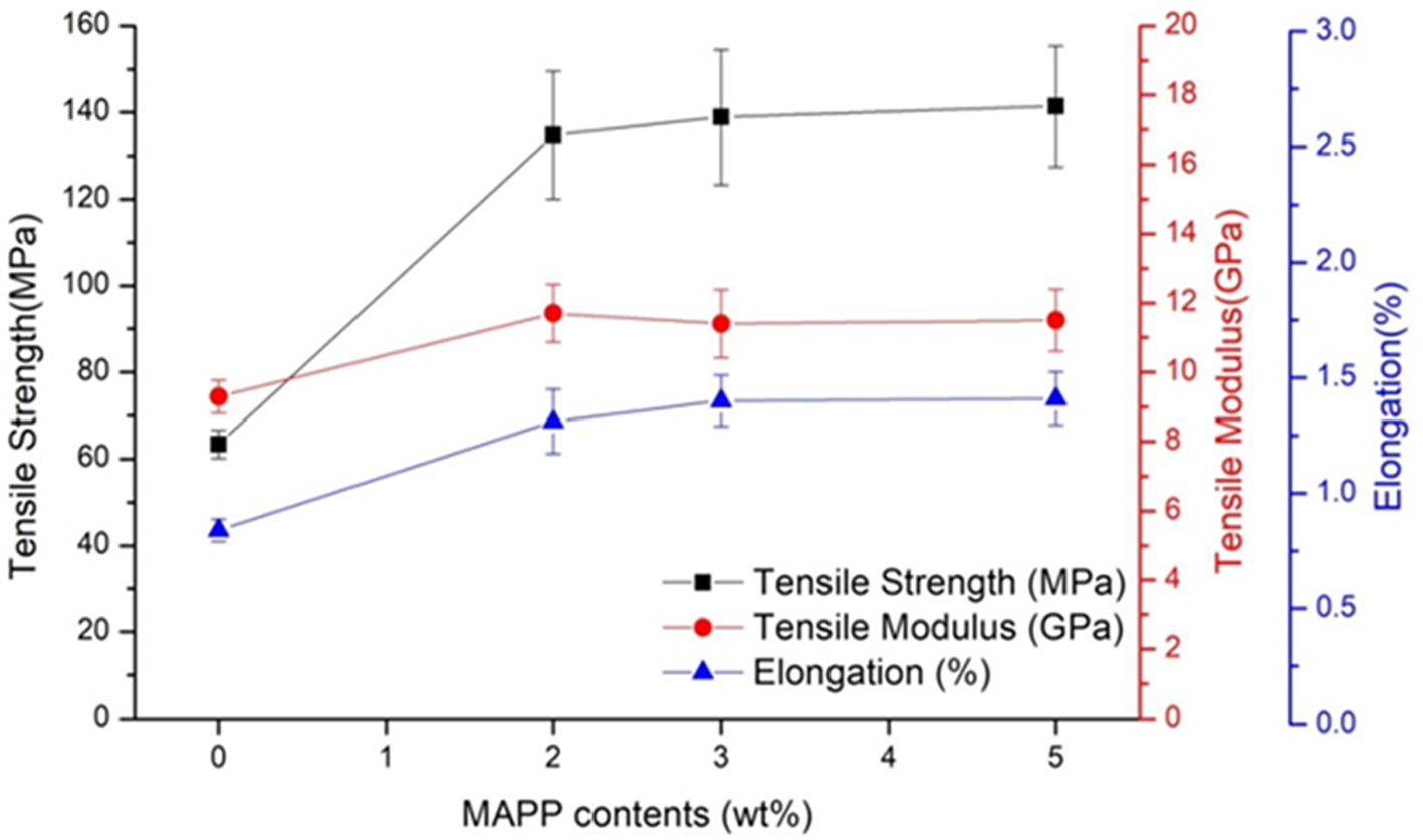
Tensile
Properties of the rCFRPs. Figure 6 shows the
tensile test results of rCFRPs with different MAPP content. As expected, the
results showed that the tensile properties were improved by using PP with MAPP
added. For the rCFRP with 2 wt% MAPP, the tensile strength was significantly
increased by 113%, the tensile modulus by 26% and the elongation by 56%
compared to the rCFRP without MAPP. This significant improvement indicates that
MAPP is contributed to the interfacial adhesion between the rCFs and PP.
Although the tensile strength was a maximum value in the rCFRP with 5 wt%
MAPP, it is considered that the effect of MAPP content on tensile properties is
slight. As MAPP content increased from 2 to 5 wt%, the tensile strength
and elongation was increased slightly while the tensile modulus was decreased
slightly. This suggests that there is a limit to the improvement of the tensile
properties by the addition of MAPP as reported in many studies.10-16
The slight effect of MAPP content on the tensile properties is believed to be
mainly attributable to excessive density of MAPP and short PP molecular chains
on the rCFs surface.
Typical stress-strain curves of the rCFRPs are shown in Figure 7. The
tensile behavior of the rCFRP without MAPP was different from the rCFRP with
MAPP. The obvious difference in tensile behavior with MAPP addition is after
the break point. The tensile stresses of the rCFRP with MAPP were rapidly
dropped after break point while tensile stress of the rCFRP without MAPP
gradually decreased. The gradual decrease implies that the friction force
during the fiber pull-out occurred after the full debonding between the rCF and
matrix.
Fractography. Figure 8 shows the
fracture surfaces were taken perpendicularly to investigate in detail the MAPP
effect contributing to the interfacial adhesion. The length of pulled-out rCFs
in rCFRP without MAPP is significant long compared to that with MAPP. The
surfaces of pulled-out rCFs in the rCFRP without MAPP are clean, while those
with MAPP are covered with the matrix. As the MAPP content increased, the
coverage matrix was thicker and frequently observed. The coverage matrix on the
rCFs implies the improvement of the interfacial adhesion because the crack
induced by the tensile test propagated into matrix instead of the interface
between the rCFs and matrix. In particular, it is interesting that the long
fibrils are frequently observed on fracture surface in the rCFRP with
5 wt% MAPP. From Figure 8(d), it is deduced that fibrillation is formed
from craze-like features between the coverage matrix on the rCFs and the bulk
matrix or between the coverage matrices of each adjacent rCFs. The craze-like
features would be initiated when the external stretch causes a micro-void to
open up at a stress concentration by a heterogeneity in the molecular network.26
It indicates that the micro-voids are favorable to be created where molecular
entanglement density is relatively low, and that their position results in the
thickness of the coverage matrix on the rCFs surface. Furthermore, the
craze-like features and fibrils indicate that enough molecular entanglement
exists on the vicinity of rCFs in the rCFRP with 5 wt% MAPP. This finding
supports the molecular entanglement was induced by the excessive MAPP molecular
density, which was discussed for the shoulder melting peak in 1st heating
thermogram of rCFRP.

|
Figure 2 Photograph of as received rCF. |

|
Figure 3 SEM images of (a) rCF fluff; (b) rCF bundle. |

|
Figure 4 XPS survey spectra (a, b); C1s high resoultion spectra (c, d) of (a, c) rCF fluff and (b, d) rCF bundle. |

|
Figure 5 DSC thermograms of rCFRPs: (a) 1st heaing; (b) 2nd heating; (c) 1st cooling. |

|
Figure 6 Tensile properites of rCFRPs. |

|
Figure 7 Typical stress-strain curves of the rCFRPs. |

|
Figure 8 Fracure surfaces of rCFRP taken perpendiculary at high magnification (×2000): (a) rCF/PP; (b) rCF/(PP+2 wt%MAPP); (c) rCF/(PP+3 wt%MAPP); (d) rCF/(PP+5 wt%MAPP). |


The rCFs and the rCF nonwovens incorporated into PP by compression
molding have been investigated. Furthermore, in order to improve the tensile
properties, the effect of MAPP on the composite has been also investigated. The
rCF is consisting of two types: fluffy and bundled rCF. Both types have
sufficient oxygen functional groups on fiber surfaces and MA group in MAPP
could react for covalent bond to fiber surface. The 2 wt% addition of MAPP
resulted in dramatic improvement of tensile properties, but the effect of the
MAPP content was small. The slight effect has been considered to be associated
with excessive molecular chain density on the rCF surface. In the rCFRP with
5 wt% addition of MAPP, the excessive molecular chain density is implied
by the shoulder peak in DSC analysis and by the craze-like features in fracture
morphology. Finally, it is seen that the shoulder peak is due to the excessive
chain density through DSC analysis result.
- 2. D. A. Baker and T. G. Rials, J. Appl. Polym. Sci., 130, 713 (2013).
-

- 3. T. Ishikawa, K. Amaoka, Y. Masubuchi, T. Yamamoto, A. Yamanaka, M. Arai, and J. Takahashi, Compos. Sci. Technol., 155, 221 (2018).
-
- 4. S. J. Pickering, Composites Part A, 37, 1206 (2006).
-
- 5. S. Pimenta and S. T. Pinho, Waste Manage., 31, 378 (2011).
-
- 6. G. Oliveux, L. O. Dandy, and G. A. Leeke, Prog. Mater. Sci., 72, 61 (2015).
-
- 7. F. Meng, J. McKechnie, T. Turner, K. H. Wong, and S. J. Pickering, Environ. Sci. Technol., 51, 12727 (2017).
-
- 8. A. Greco, A. Maffezzoli, G. Buccoliero, F. Caretto, and G. Cornacchia, J. Compos. Mater., 47, 369 (2013).
-
- 9. H. Lee, I. Ohsawa, and J. Takahashi, Appl. Surf. Sci., 328, 241 (2015).
-
- 10. M. Szpieg, K. Giannadakis, and L. E. Asp, J. Compos. Mater., 46, 1633 (2012).
-
- 11. K. H. Wong, D. S. Mohammed, S. J. Pickering, and R. Brooks, Compos. Sci. Technol., 72, 835 (2012).
-
- 12. G. Luo, W. Li, W. Liang, G. Liu, Y. Ma, Y. Niu, and G. Li, Compos. Part-B Eng., 111, 190 (2017).
-
- 13. A. Arbelaiz, B. Fernandez, J. A. Ramos, A. Retegi, R. Llano-Ponte, and I. Mondragon, Compos. Sci. Technol., 65, 1582 (2005).
-
- 14. A. R. Sanadi, D. F. Caulfield, R. E. Jacobson, and R. M. Rowell, Ind. Eng. Chem. Res., 34, 1889 (1995).
-
- 15. W. Qiu, T. Endo, and T. Hirotsu, Eur. Polym. J., 42, 1059 (2006).
-
- 16. A. K. Rana, A. Mandal, and S. Bandyopadhyay, Compos. Sci. Technol., 63, 801 (2003).
-
- 17. B. A. Acha, M. M. Reboredo, and N. E. Marcovich, Polym. Int., 55, 1104 (2006).
-
- 18. L. Giorgini, T. Benelli, L. Mazzocchetti, C. Leonardi, G. Zattini, G. Minak, E. Dolcini, M. Cavazzoni, I. Montanari, and C. Tosi, Polym. Compos., 36, 1084 (2015).
-
- 19. L. Jiang, C. A. Ulven, D. Gutschmidt, M. Anderson, S. Balo, M. Lee, and J. Vigness, J. Appl. Polym. Sci., 132, 42658 (2015).
-
- 20. L. O. Meyer, K. Schulte, and E. Grove-Nielsen, J. Compos. Mater., 43, 1121 (2009).
-
- 21. G. Jiang and S. J. Pickering, J. Mater. Sci., 51, 1949 (2016).
-
- 22. E. Desimoni, G. I. Casella, A. Morone, and A. M. Salvi, Surf. Interface Anal., 15, 627 (1990).
-
- 23. W. H. Lee, J. G. Lee, and P. J. Reucroft, Appl. Surf. Sci., 171, 136 (2001).
-
- 24. Y. Wang, H. Viswanathan, A. A. Audi, and P. M. Sherwood, Chem. Mater., 12, 1100 (2000).
-
- 25. K. Cho, F. Li, and J. Choi, Polymer, 40, 1719 (1999).
-
- 26. Y. Seo, J. Kim, K. U. Kim, and Y. C. Kim, Polymer, 41, 2639 (2000).
-
- 27. R. A. C. Deblieck, D. J. M. van Beek, K. Remerie, and I. M. Ward, Polymer, 52, 2979 (2011).
-
- Polymer(Korea) 폴리머
- Frequency : Bimonthly(odd)
ISSN 0379-153X(Print)
ISSN 2234-8077(Online)
Abbr. Polym. Korea - 2023 Impact Factor : 0.4
- Indexed in SCIE
 This Article
-
2020; 44(1): 109-115
Published online Jan 25, 2020
- 10.7317/pk.2020.44.1.109
- Received on Oct 21, 2019
- Revised on Nov 6, 2019
- Accepted on Nov 10, 2019
Services
- Full Text PDF
- Abstract
- ToC
- Acknowledgements
Introduction
Experimental
Results and Discussion
Conclusions
- References
Shared
Correspondence to
- Han-Yong Jeon
-
Department of Chemical Engineering, Inha University, 100 Inha-ro, Michuhol-gu, Incheon 22212, Korea
- E-mail: hyjeon@inha.ac.kr
- ORCID:
0000-0003-2432-6884
Hyecheon Building(Room 601), #354, Gangnam-Daero, Gangnam-Gu, Seoul 06242, Korea
TEL : 82-2-568-3860, 561-5203, 569-3860 FAX : 82-2553-6938 E-mail: polymer@polymer.or.kr