


- Effects of Molecular Weight of Polyvinylidene Fluoride Binder on Electrochemical Performances of Organic Electric Double-Layer Capacitors
Jihoon Yoo#,*, Inchan Yang#,*, Myung-Soo Kim*, and Ji Chul Jung*,**,†

*Department of Chemical Engineering, Myoungji University, Yongin 17058, Korea
**Organic-Inorganic Hybrid Process Research Center, Myongji University, Yongin 17058, Korea
- 플루오르화 폴리비닐리덴 바인더의 분자량이 유기계 전기이중층 커패시터의 전기화학적 특성에 미치는 영향
유지훈#,* · 양인찬#,* · 김명수* · 정지철*,**,†
*명지대학교 화학공학과, **명지대학교 유무기 하이브리드 공정연구소
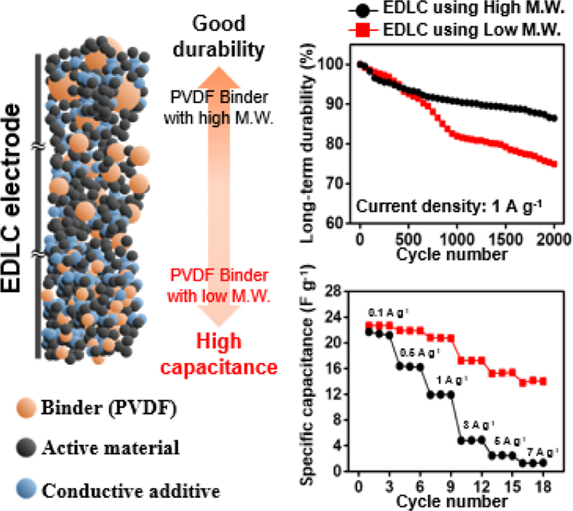
Herein, we assembled electric
double-layer capacitor (EDLCs) electrodes with polyvinylidene fluoride (PVDF)
as the binder. The effect of the molecular weight of PVDF on the
electrochemical properties of the EDLCs were investigated by various
characterization tools. The EDLCs assembled using PVDF with low molecular
weight showed relatively good capacitance compared to those assembled using
PVDF with high molecular weight owing to their low resistance. However, in
long-term durability experiments, EDLCs assembled using PVDF with high
molecular weights showed higher durability than EDLCs assembled using PVDF with
low molecular weights. To investigate the underlying reasons, field
emission-scanning electron microscopy (FE-SEM) was applied. Although all
prepared EDLC electrodes showed tightly packed morphologies before
charge–discharge process was conducted, morphologies of electrodes using low molecular
weight PVDF were gradually loosed as charge–discharge process was conducted. As
a result, an appropriate binder molecular weight is required to prepare EDLC
with high performances.
본 논문에서는 바인더가 유기계 전기이중층 커패시터(EDLCs)의 전기화학적 성질에 미치는 영향을 조사하기 위하여 플루오르화 폴리비닐리덴(polyvinylidene fluoride, PVDF) 바인더의 분자량을 다르게 하여 EDLC를 조립한 후 다양한 전기화학적 특성 분석을 실시하였다. 특성
분석 결과, 낮은 분자량의 PVDF를 사용하여 조립된 EDLC는 높은 분자량의 PVDF를 사용하여 조립된 EDLC보다 낮은 저항 및 높은 용량 특성을 나타냈으나 충-방전이
진행되는 동안 활물질과 도전재 사이의 구조가 높은 분자량의 PVDF를 사용하여 조립된 EDLC에 비해 느슨해져 결과적으로 낮은 수명을 나타내었다. 따라서
높은 성능을 갖는 EDLC를 제조하기 위해서는 적절한 바인더 분자량이 요구된다
The effect of the molecular weight of polyvinylidene
fluoride (PVDF) on the electrochemical properties of the electric double-layer
capacitor (EDLCs) were investigated by various characterization tools. The
EDLCs using PVDF with low molecular weight exhibited high capacitance, while
those using PVDF with high molecular weight showed good durability. As a
result, an appropriate binder molecular weight is required to prepare EDLC with
high performances.
Keywords: electric double-layer capacitor, binder, molecular weight, rate capability, cycle stability
This research was supported by Basic Science Research
Program through the National Research Foundation of Korea(NRF) funded by the
Ministry of Education (2018R1D1A1B07048128).
Electric double-layer capacitors (EDLCs), a type of supercapacitor, have
been actively studied as electrical energy storage devices.1-6 EDLCs
use charge separation in a Helmholtz double-layer at the interface between the
electrode surface and electrolyte.1-4 Accordingly, EDLCs have many
advantages including fast charge-discharge rate,
durable life cycle, and high power density compared to secondary batteries
using various chemical reactions for charge-discharge processes. Thus, EDLCs
have great potential for important applications in many fields, and significant
attempts to develop EDLCs with better electrochemical performance have been
made.7,8 Particularly, many studies on electrode materials,
including active materials, conductive additives, and binders have been
conducted to enhance the electrochemical performances of EDLCs.9-11
Electrode materials for EDLCs are generally classified as active
materials, conductive additives, or binders.12-16 Porous carbon
materials are widely used as active materials as they can store electrical
energy to form a Helmholtz double-layer. Commercially, activated carbons such
as YP series (Kuraray Co.), MSP20 (Kansai Coke & Chemicals Co.), and CEP
series (Power Carbon Technology Co.) are used as active materials (Table 1).17-19
In addition, nanocarbon
materials with high specific surface area21-31 and carbon aerogels
or carbon xerogels32-38 have been recently used as active materials
for studies on EDLCs and have shown high performances. As conductive additives,
carbon blacks are generally used due to their high conductivity arising from
their well-connected structure. Binders can be classified as organic or aqueous
binders. Polyvinylidene fluoride (PVDF) is a representative organic binder,
while polytetrafluorethylene (PTFE) is a representative aqueous binder. In
EDLCs, binders are important for combining active materials and conductive
additives, and to attach electrode materials to the current collector. Polymers
are often used as binders, but overuse of binders leads to high resistance of
the assembled EDLCs. Accordingly, binders are well-known to have a strong
effect on electrode resistance. Thus, binders are important electrode materials
and highly influence the electrochemical performances of the EDLCs.
Nevertheless, studies regarding binders for EDLCs are quite rare compared to
those on active materials and conductive additives. Therefore, we investigated
the effects of binders on the electrochemical performances of EDLCs using three
different molecular weights. Herein, YP50F and Super-P were applied as an
active material and conductive additive, respectively. To thoroughly
investigate the effects of molecular weight of binder on EDLCs, various
characterization tools including cyclic voltammetry, galvanostatic
charge–discharge, four-point probe, electrochemical impedance spectroscopy, and
field emission-scanning electron microscopy (FE-SEM) were used.
|
Table 1 Physical Properties of the Commercially Available Activated Carbons20 |
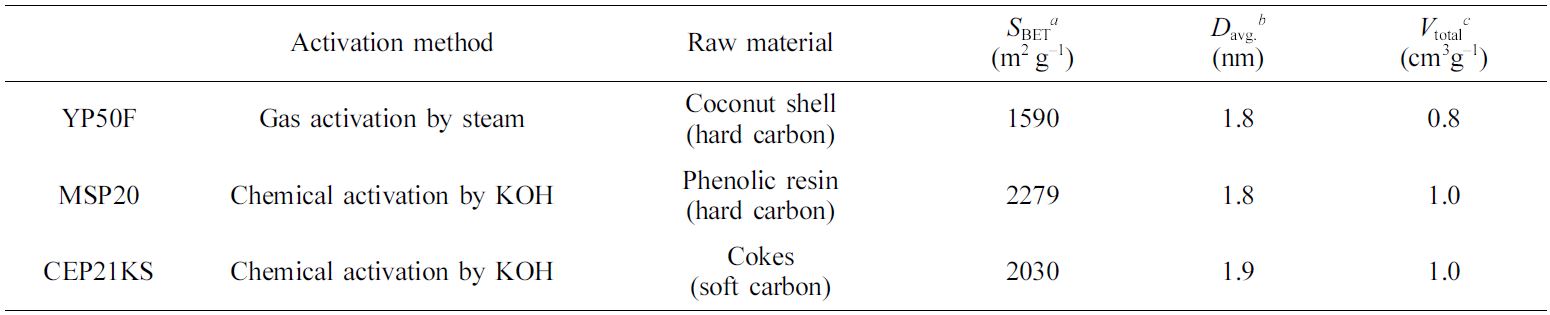
aSpecific surface area: calculated by the Brunauer–Emmett–Teller (BET) plot. bAverage pore diameter: determined by the Barret–Joyner–Hallender (BJH) method with the desorption branch. cTotal pore volume. |
Preparation
of EDLCs. All chemicals were
used without further purification after purchase. As an active material, YP50F
(Kuraray Co.), a representative active material in commercial EDLCs, was
applied and Super-P (MMM Carbon Co.) was used as a conductive additive. In
addition, PVDF (Sigma-Aldrich) with three different molecular weights were
dissolved in 1-methyl-2-pyrrolidon (NMP, Daejung) and mixed as binders. Herein,
three different molecular weights of PVDF are 180000, 275000, and 534000.
First, the active material and conductive additive were mixed for 30 min
using a ball-mill to obtain a homogeneous powder-type mixture. Afterwards, the
prepared PVDF binder was added to the powdered mixture of the active material
and conductive additive to prepare the electrode materials in the form of a
slurry-type mixture. Subsequently, the slurry composed of the electrode
materials was vigorously stirred for 1 h. The mass ratio of active material,
conductive additive, and binder was fixed at 8:1:1. A homogeneous slurry-type
mixture was coated on the current collector with a gap of 23 μm using a
blade apparatus. Following the coating, the coated electrode was dried at
70 oC in vacuo for 24 h, and pressed using a double-roll
press at 80 oC. After drying, the circular electrodes
(18 mm in diameter) were obtained using a punching apparatus to assemble
coin-type EDLCs (CR2030-battery-size). Finally, coin-type EDLCs were assembled
using the prepared electrodes, separator, and spacer. The electrodes were
soaked in an organic electrolyte (1 M tetraethylammonium tetrafluoroborate in
acetonitrile; TEABF4/ACN) for 12 h in a glovebox filled with
nitrogen gas. The soaked electrodes were placed opposite of each other and a
separator was loaded between the electrodes. The EDLCs was sealed using a
coin-cell crimper (Wellcos Co.). Thus, we finally obtained EDLCs using binders
with different molecular weights, which were named according to the applied molecular
weight of the binder (PVDF_X, X = molecular weight of binder * 10–3 = 180,
275, and 534).
Electrochemical
Characterization of EDLCs. To confirm the
electrochemical properties of the prepared EDLCs, we performed cyclic voltammetry
(CV, CS310, CorrTest), galvanostatic charge–discharge analysis (C–D, CS310,
CorrTest), four-point probe measurement (FPP, CMT-SR1000N, Advanced Instrument
Technology), and EIS (CS310, CorrTest).
We recorded CV curves at
various scan rates ranging from 5 to 100 mVs−1 in voltage range of
0–2.7 V. We also obtained C–D results at constant current loads from 0.1 to
7 Ag–1 at a fixed voltage range. The specific capacitances (gravimetric
capacitance (Cg) and volumetric capacitance (Cv))
of the EDLCs were calculated using the discharge curve from the
C–D measurements. The Cv values of the EDLCs were obtained by
multiplying Cg and the electrode density (ρelectrode). The ρelectrode value was determined from the
ratio of the loading mass of active materials to the total electrode volume. To
confirm the resistance properties of the prepared EDLCs, FPP and EIS
measurements were performed. Through the FPP measurements, we directly
confirmed the sheet resistances of the EDLCs. Through the EIS analysis we
confirmed the charge-transfer resistance (Rct) and were used
to show results of the EIS analysis over a frequency range of 100 kHz to 0.01
Hz. To investigate the long-term durability of the EDLCs, the C–D of 2000
cycles was measured. The durability test was conducted at constant current loads
of 1 Ag−1 at a voltage range of 0 to 2.7 V. In addition,
field emission–scanning electron microscopy (FE-SEM, SU-70, Hitach) was used to
confirm the morphological changes of the EDLC electrodes during the C–D of 2000
cycles.
Capacitance Properties of the EDLCs. First, we will
describe some differences between two- and three-electrode (2E and 3E)
systems for understanding the capacitance properties of EDLCs before discussing
these properties of the prepared EDLCs. Although the majority of researchers
use the 3E system, a 2E system was used in this study to
measure the capacitances of the EDLC cells. This is because using the 2E
system would have more industrial worth compared with using the 3E
system. Assuming that each EDLC electrode has the same weight, the following
equation relates the specific capacitances determined using a 3E
system and 2E system.39
 (1)
(1)
Where C is the specific capacitance. Therefore, eq. (1) can be
used to analyze the capacitance properties determined using a 3E
system. Herein, we successfully configured a 2E system to measure
the electrochemical properties.
The CV results at various scan rates (10, 50, 100, and 300 mVs−1)
are shown in Figure 1.
At scan rate of 10 mV s−1, which was the lowest scan rate
used in this study, all prepared EDLCs showed CVs with a rectangular shape.
However, with increasing scan rate, the CV areas of PVDF_275 and PVDF_534
rapidly decreased, whereas that of PVDF_180 showed a fairly well-maintained
rectangular shape even at the highest scan rate. To summarize the CV results,
all prepared EDLCs exhibited good capacitance properties at 10 mVs−1,
but the capacitance properties of PVDF_275 and PVDF_534 rapidly decreased with
increasing scan rate. From this trend, we inferred that the molecular weight of
binder highly influenced the capacitance properties of the EDLCs at high-rate
of C–D. To confirm this trend, we conducted C–D tests and the obtained results
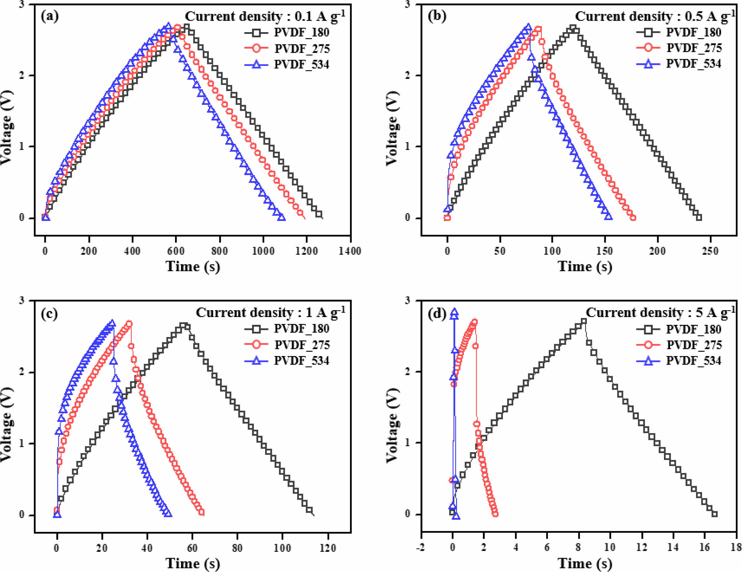
are shown in Figure 2. Moreover, the specific capacitances calculated from C–D
results are presented in Figure 3 and Table 2.
The formulas for the specific capacitance calclated from the C–D results
are as follows.
 (2)
(2)
 (3)
(3)
where Cg is the gravimetric capacitance, Cv
is the volumetric capacitance, I is the discharge current, Δt is
the time required for discharge, m is the weight of the two electrode
materials, ΔV is the change in voltage during discharge, and ρelectrode is the density of the active
materials on the electrodes determined from the ratio of loading mass to volume
of the electrode materials. We obtained the same trend as observed for the CV
results. Although all prepared EDLCs showed good capacitance properties at a
low C–D rate (1 Ag−1), the capacitance properties of EDLCs
using binders with high molecular weight rapidly decreased with increasing rate
of C–D. In other words, the EDLCs prepared with binders of low molecular weight
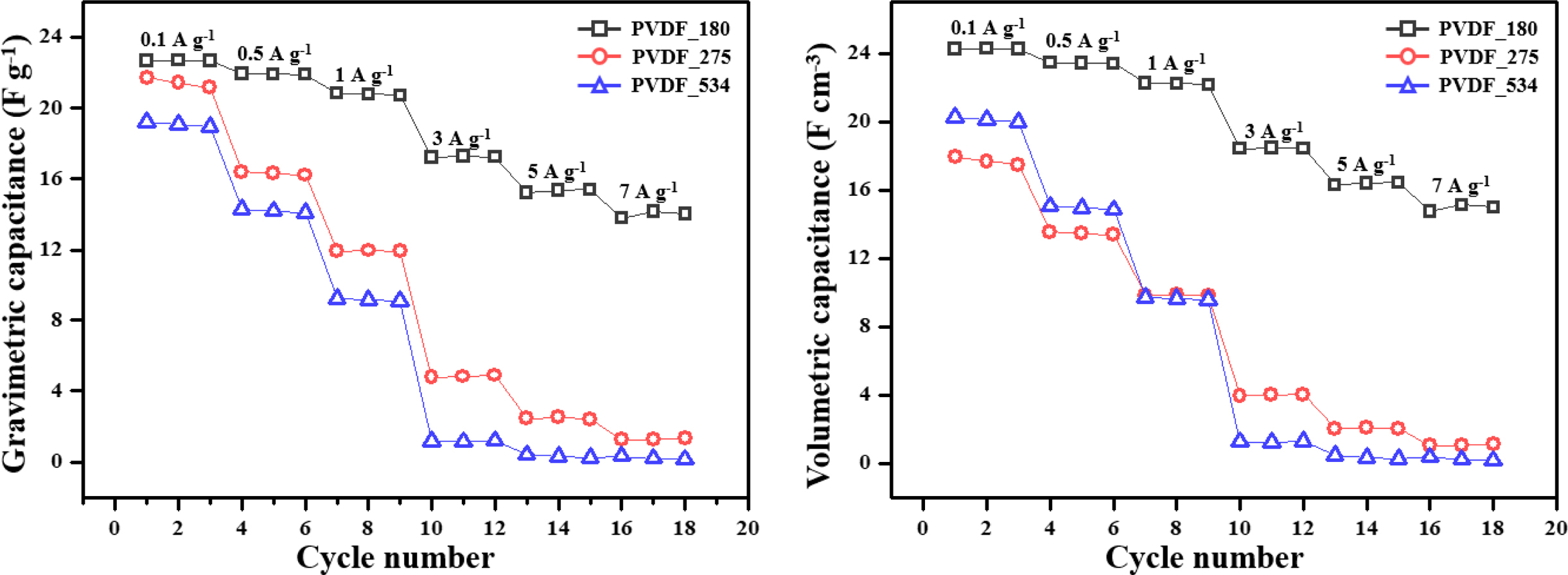
showed good rate capability. To compare the rate capability of the prepared
EDLCs, retention ratios of gravimetric capacitance were calculated, and the
obtained results are presented in Table 2. The retention ratios were determined
from the ratios of gravimetric capacitance at 0.1 and 7 Ag−1. The
EDLC prepared with low molecular weight binder showed a high retention ratio,
while the EDLC with high molecular weight binder showed a lower retention
ratio.
To summarize, we investigated effects of molecular weight of the PVDF
binder on the capacitance properties of the EDLCs. The prepared EDLCs showed
relatively high capacitances at low C–D rates, where capacitances were
gradually reduced with increasing rates. The EDLCs showed different rate
capabilities, where the EDLCs prepared using binders with high molecular weight
showed poor rate capability. Thus, we concluded that the capacitance properties
of EDLCs are highly influenced by the molecular weight of binders at a high C–D
rate compared to the low-rate range. Moreover, based on our previous studies,
the electrical conductivity of the electrode materials is a crucial factor at
high C–D rates.40 Therefore, we predicted that the difference of
EDLC rate capabilities originated from differences in the resistance properties
of the EDLCs prepared with different molecular weights of PVDF binder.
Resistance
Properties of the EDLCs. To confirm the
resistance properties of the EDLCs prepared using binder with three different
molecular weights, we conducted FPP measurements and EIS analysis (Table 3 and
Figure 4).
In the FPP results, PVDF_180 showed the lowest resistance, as predicted
from its corresponding capacitance properties. Furthermore, the sheet
resistance increased with increasing molecular weight of the binder. To clearly
confirm the resistance properties, EIS analysis was performed and the results
were represented by Nyquist plots, which is representative plot to present the
EIS results. Prior to discussing the resistance performances of the prepared
EDLCs, we will first explain the generation of Nyquist plots from EIS
measurements. The Nyquist plots can be divided into three regions. The first is
the region from which the bulk solution resistance (Rs) can
be deduced from the x-intercept where the initial graph begins in the
high-frequency range. Rs appears differently depending on the
electrolyte and solvent used and is related to migration of the electrolyte
ions far from the electrode. The semi-circular region, which appears in the
intermediate frequency range, is a region that can be used as an index
representing the charge transfer resistance (Rct). They can
be divided into electron transfer and ion transfer resistance. The ion transfer
resistance is related to charge transfer through the movement of the
electrolyte ion into the structural pores between the relatively large active
material particles, and can be interpreted as resistance to the movement of
electrons in the electrode and the movement of electrons between the electrode
and current collector. Finally, the Warburg response region is related to
migration of the electrolyte ions in the micropores of the electrode material
in the low-frequency range. When all pores are saturated with electrolyte ions,
the Warburg response region ends and a linear region with a sharp increase
close to parallel to the y-intercept is displayed.41-43 As
shown in Figure 4, the results of EIS were in good agreement with those of FPP.
Particularly, the Rct trends determined by the radius of the
semi-circle decreased in the order of: PVDF_534, PVDF_273, and PVDF_180. As a
result, the Rct of the EDLCs decreased with increasing
molecular weight of PVDF binder. One cause of this phenomenon is that the
distance between the active material and conductive additive in the electrode
gradually decreases as the molecular weight of the binders decreased. In other
words, the low molecular weight of the binder brings the electrode materials in
the EDLCs relatively closer together compared to the high molecular weight
binders. This results in low resistance properties and good rate capability of
the resulting EDLCs. Considering our previous studies regarding the
relationship between the capacitance properties and resistance properties of
EDLCs,40 the resistance results presented herein are good agreement
with capacitance properties.
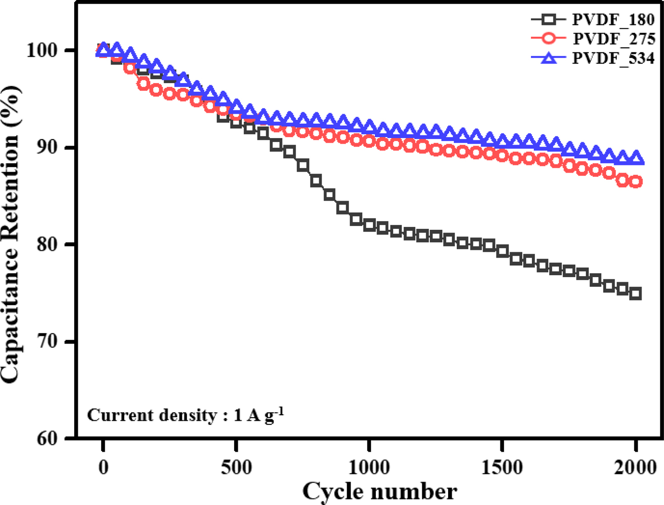
Long-term
Durability of the EDLCs. To confirm the
long-term durability of the prepared EDLCs, 2000 C–D cycles were performed. For
confirmation, we used a current density of 1 A g–1 because all
prepared EDLCs showed good and similar capacitance results at this current
density. The obtained results are shown in Figure 5.
Interestingly, contrasting results to the capacitance and resistance
results were obtained. From the results of capacitance and resistance, the EDLC
prepared using PVDF binder with the lowest molecular weight showed the best
performances among the prepared EDLCs. However, the durability of PVDF_180
rapidly decreased as the number of C–D cycles increased. In contrast, PVDF_275
and PVDF_534, which showed relatively poor rate capabilities due to their high
resistances, showed well-maintained capacitance properties during the 2000 C–D
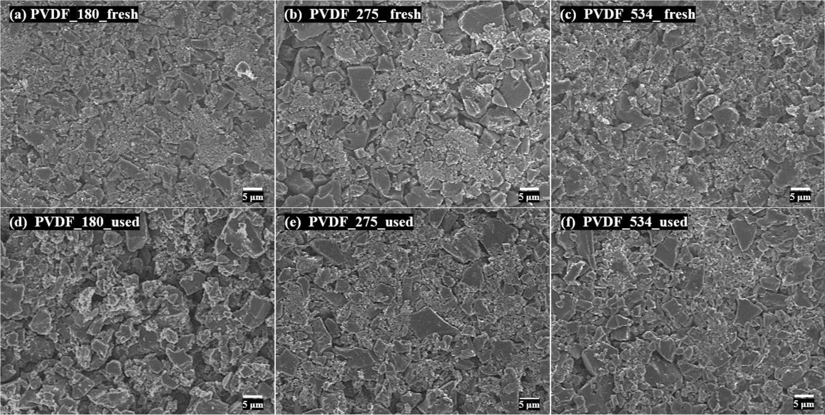
cycles. To investigate the causes of the obtained durability results, we
directly confirmed the morphological changes of the electrode surface during
the 2000 C–D cycles through FE-SEM images (Figure 6). Initially, it was
observed that the active material and conductive additives of all prepared EDLC
electrodes were tightly packed. As the 2000 C–D cycles progressed, these
tightly packed morphologies were separated. Herein, PVDF_275 and PVDF_534
showed small gaps between the electrode materials compared to PVDF_180. As a
result, we concluded that differences in the spacing change during C–D cycling
governs the durability of the prepared EDLCs, and the binders with high
molecular weight formed EDLCs with good long-term durability.
Binders play an important role
connecting active materials and conductive additives in EDLC electrodes.
However, when the molecular weight of binder is too low, the binder cannot
maintain the connection of the active material and conductive additive during
long-term C–D cycling, resulting in poor capacitance properties of the EDLCs.
Through our previous studies, we confirmed that connection of the active
material and conductive additive in EDLC electrodes highly influenced the
electrochemical performances of EDLCs.44 Furthermore, we concluded
that an appropriate molecular weight of the binder is required for optimal EDLC
performance with high cycle stability and good electrochemical performance.
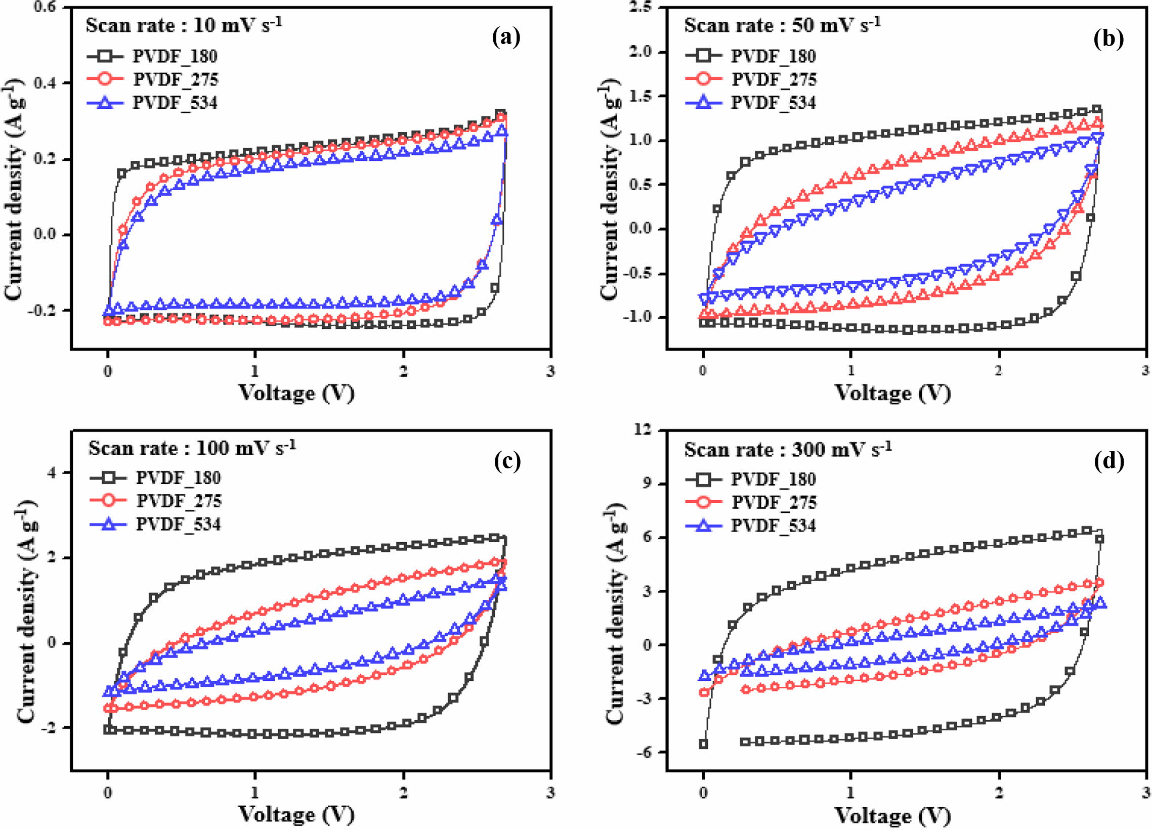
|
Figure 1 Cyclic voltammograms of the electric double-layer capacitors at a fixed scan rate: (a) 10 mVs–1; (b) 50 mVs–1; (c) 100 mVs–1; (d) 300 mVs–1. |
|
Figure 2 Galvanostatic charge–discharge profiles of the electric double-layer capacitors at a constant current density of (a) 0.1 Ag–1; (b) 0.5 Ag–1; (c) 1 Ag–1; (d) 5 Ag–1. |
|
Figure 3 Specific capacitances of the electric double-layer capacitors. |

|
Figure 4 Electrochemical impedance spectra of the electric double-layer capacitors. |
|
Figure 5 Long-term durability of the electric double-layer capacitors. |
|
Figure 6 FE-SEM images of electrodes of the electric double-layer capacitors. (a), (b), (c): fresh; (d), (e), (f): used. |
|
Table 2 Specific Capacitances and Retention Ratios of the Prepared Electric Double-Layer Capacitors |
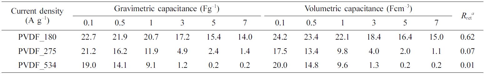
aRetention ratio with increasing charge–discharge rate: calculated from the ratio of gravimetric capacitances at 0.1 and 7 Ag–1. |
|
Table 3 Sheet Resistances of the Electric Double-Layer Capacitors |
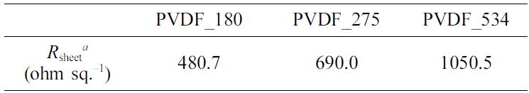
aSheet resistance: confirmed by four-point probe measurement. |
Herein, we thoroughly investigated the effects of the molecular weight of the binder on the electrochemical performances of EDLCs. For this investigation, we prepared EDLCs using PVDF binders with three different molecular weights. As an active material and conductive additive, we used a commercial activated carbon and carbon black, respectively. Through electrochemical characterization, we confirmed that the binder molecular weight strongly affected the electrochemical performances of EDLCs. All prepared EDLCs showed considerable capacitance at low C–D rates, but differences in electrochemical performances at high C–D rates were observed. EDLCs prepared using a PVDF binder with low molecular weight showed good rate capability and low resistance properties compared to those prepared using PVDF binders with high molecular weights. In other words, EDLCs prepared using PVDF binders with high molecular weight showed poor electrochemical performance at high C–D rates. However, in the long-term durability test, contrasting results were obtained. The capacitance properties of the EDLCs prepared using PVDF binders with low molecular weights rapidly decreased with increasing number of C–D cycles. In contrast, EDLCs prepared using PVDF binders with high molecular weights exhibited relatively well-maintained capacitances during the long-term durability test. The FE-SEM images confirmed that the differences in durability originated from the spacing of electrode materials as C–D analysis was conducted. It was concluded that the molecular weight of the binder strongly affected the electrochemical performances of the prepared EDLCs, and that an appropriate molecular weight of binder is required for realizing EDLCs with high cycle stability and good electrochemical performance.
- 1. E.Frackowiak, Q. Abbas, and F. Béguin, J. Energy Chem., 22, 226(2013).
-

- 2. A. González, E. Goikolea, J. A. Barrena, and R. Mysyk,Renew. Sustain. Energy Rev., 58, 1189 (2016).
-
- 3. L.Zhang, X. Hu, Z. Wang, F. Sun, and D. G. Dorrell, Renew. Sustain. EnergyRev., 81, 1868 (2018).
-
- 4. R. Burt, G. Birkett, and X. S. Zhao, Phys. Chem.Chem. Phys., 16, 6519 (2014).
-
- 5. G. Wang, L. Zhang, and J. Zhang, Chem. Soc. Rev.,41, 797 (2012).
-
- 6. T.Sato, S. Marukane, T. Morinaga, T. Kamijo, H. Arafune, and Y. Tsujii, J.Power Sources, 295, 108 (2015).
-
- 7. J. R. Miller and P. Simon, Science, 321,651 (2008).
-
- 8. P. Thounthong, V. Chunkag, P. Sethakul, S. Sikkabut,S. Pierfederici, and B. Davat, J. Power Sources, 196, 313 (2011).
-
- 9. Z. Yu, L. Tetard, L. Zhai, and J. Thomas, EnergyEnviron. Sci., 8, 702 (2015).
-
- 10. E. Frackowiak and F. Béguin, Carbon, 39,937 (2001).
-
- 11. P. Simon and Y. Gogotsi, Nat. Mater., 7,845 (2008).
-
- 12. A. G. Pandolfo and A. F. Hollenkamp, J. PowerSources, 157, 11 (2006).
-
- 13. M. Inagaki, H. Konno, and O. Tanaike, J. PowerSources, 195, 7880 (2010).
-
- 14. N. Jäckel, D. Weingarth, M. Zeiger, M. Aslan, I.Grobelsek, and V. Presser, J. Power Sources, 272, 1122 (2014).
-
- 15. M. S. Michael and S. R. S. Prabaharan, J. PowerSources, 136, 250 (2004).
-
- 16. Z. Zhu, S. Tang, J. Yuan, X. Qin, Y. Deng, R. Qu, andG. M. Haarberg, Int. J. Electrochem. Sci., 11, 8270 (2016).
-
- 17. C. Zhang, K. B. Hatzell, M. Boota, B. Dyatkin, M.Beidaghi, D. Long, W. Qiao, E. C. Kumbur, and Y. Gogotsi, Carbon, 77,155 (2014).
-
- 18. T. Kim and J. Yoon, J. Electroanal. Chem., 704,169 (2013).
-
- 19. H. Shin, M. Agostini, I. Belharouak, J. Hassoun, andY. Sun, Carbon, 96, 125 (2016).
-
- 20. I. Yang, D. Kwon, M.-S. Kim, and J. C. Jung, Carbon,132, 503 (2018).
-
- 21. K. H. An, W. S. Kim, Y. S. Park, Y. C. Choi, S. M.Lee, D. C. Chung, D. J. Bae, S. C. Lim, and Y. H. Lee, Adv. Mater., 13,497 (2001).
-
- 22. Y. Rangom, X. Tang, and L. F. Nazar, ACS Nano, 9,7248 (2015).
-
- 23. E. Frackowiak, K. Metenier, V. Bertagna, and F.Beguin, Appl. Phys. Lett., 77, 2421 (2000).
-
- 24. N. Venugopal and W.-S. Kim, Korean J. Chem.Eng., 32, 1918 (2015).
-
- 25. Y. Wang, Z. Shi, Y. Huang, Y. Ma, C. Wang, M. Chen,and Y. Chen, J. Phys. Chem. C, 113, 13103 (2009).
-
- 26. C. Liu, Z. Yu, D. Neff, A. Zhamu, and B. Z. Jang, NanoLett., 10, 4863 (2010).
-
- 27. J. R. Miller, R. A. Outlaw, and B. C. Holloway, Electrochim.Acta, 56, 10443 (2011).
-
- 28. Z. Liu, S. Liu, R. Dong, S. Yang, H. Lu, A. Narita, X.Feng, and K. Müllen, Small, 13, 1603388 (2017).
-
- 29. H. Pan, J. Li, and Y. P. Feng, Nanoscale Res. Lett.,5, 654 (2010).
-
- 30. Z. Li, M. S. Akhtar, and O. Yang, J. Alloys Compd.,653, 212 (2015).
-
- 31. C. Kim, J. Power Sources, 142, 382(2005).
-
- 32. S. J. Kim, S. W. Hwang, and S. H. Hyun, J. Mater.Sci., 40, 725 (2005).
-
- 33. J. Li, X. Wang, Q. Huang, S. Gamboa, and P. J.Sebastian, J. Power Sources, 158, 784 (2006).
-
- 34. A. Halama, B. Szubzda, and G. Pasciak, Electrochim.Acta, 55, 7501 (2010).
-
- 35. C. H. J. Kim, D. Zhao, G. Lee, and J. Liu, Adv.Funct. Mater., 26, 4976 (2016).
-
- 36. Y. J. Lee, J. C. Jung, J. Yi, S.-H. Baeck, J. R. Yoon,and I. K. Song, Curr. Appl. Phys., 10, 682 (2010).
-
- 37. I. Yang, S.-G. Kim, S. H. Kwon, J. H. Lee, M.-S. Kim,and J. C. Jung, Curr. Appl. Phys., 16, 665 (2016).
-
- 38. I. Yang, S.-G. Kim, S. H. Kwon, M.-S. Kim, and J. C.Jung, Electrochim. Acta, 223, 21 (2017).
-
- 39. D. Qu and H. Shi, J. Power Sources, 74,99 (1998).
-
- 40. I. Yang, D. Kwon, J. Yoo, M.-S. Kim, and J. C. Jung,Curr. Appl. Phys., 19, 89 (2019).
-
- 41. H. D. Yoo, J. H. Jang, J. H. Ryu, Y. Park, and S. M.Oh, J. Power Sources, 267, 411 (2014).
-
- 42. C. Portet, P. L. Taberna, P. Simon, and L. Robert, Electrochim.Acta, 49, 905 (2004).
-
- 43. C. Lei, F. Markoulidis, Z. Ashitaka, and C. Lekakou, Electrochim. Acta, 92, 183 (2013).
-
- 44. I. Yang, S. H. Kwon, B.-S. Kim, S.-G. Kim, B.-J. Lee,M.-S. Kim, and J. C. Jung, Korean J. Mater. Res., 25, 132 (2015).
-
- Polymer(Korea) 폴리머
- Frequency : Bimonthly(odd)
ISSN 0379-153X(Print)
ISSN 2234-8077(Online)
Abbr. Polym. Korea - 2023 Impact Factor : 0.4
- Indexed in SCIE
 This Article
-
2019; 43(6): 838-845
Published online Nov 25, 2019
- 10.7317/pk.2019.43.6.838
- Received on Jun 10, 2019
- Revised on Aug 12, 2019
- Accepted on Aug 23, 2019
Services
- Full Text PDF
- Abstract
- ToC
- Acknowledgements
Introduction
Experimental
Results and Discussion
Conclusions
- References
Shared
Correspondence to
- Ji Chul Jung
-
*Department of Chemical Engineering, Myoungji University, Yongin 17058, Korea
**Organic-Inorganic Hybrid Process Research Center, Myongji University, Yongin 17058, Korea
- E-mail: jcjung@mju.ac.kr
- ORCID:
0000-0002-3983-9407
Hyecheon Building(Room 601), #354, Gangnam-Daero, Gangnam-Gu, Seoul 06242, Korea
TEL : 82-2-568-3860, 561-5203, 569-3860 FAX : 82-2553-6938 E-mail: polymer@polymer.or.kr