


- Effect of Alumina Trihydrate on Intumescent Flame Retardant Polymer Composite Coatings
Riyazuddin, Tentu Nageswara Rao, Imad Hussain, S. N. Khan*, and Bon Heun Koo†

School of Materials Science and Engineering, Changwon National University, Changwon, Gyeongnam 51140, Korea *Department of Physics, Abdul Wali Khan University Mardan, Pakistan
- 팽창성 난연 고분자 복합체 코팅에 대한 알루미나 삼수화물의 효과
Riyazuddin · Tentu Nageswara Rao · Imad Hussain · S. N. Khan* · 구본흔†
창원대학교 신소재공학부, *압둘 왈리 칸 대학교 물리학과
A charring-foaming agent (CFA)
polymer was synthesized via a nucleophile substitution reaction and used in
intumescent flame retardant (IFR) coating preparations. The CFA structure was
characterized by Fourier transform infrared spectroscopy (FTIR) and elemental
analysis. The IFR system was composed of the ammonium polyphosphate (APP) and a
foaming agent (CFA). APP and CFA were fixed at 2:1 ratio and different amount
of alumina trihydrate (ATH) are loaded into an epoxy resin to prepare IFR
coating compositions. The TGA results showed that the addition of ATH greatly
increased the char residue percentage of the coatings at 800 oC.
The UL-94V data indicated that the V-0 ratings were obtained with the addition
of ATH into coatings. The cone calorimeter data showed that the peak heat
release rates (PHRR) and total heat releases (THR) of the coatings remarkably
decreased with the increase of ATH loading. The incorporation of ATH into
epoxy/IFR enhanced the thermal stability and incombustible behavior of the
coating system.
탄화 발포제(CFA) 폴리머는
친핵체 치환 반응을 통해 합성되며 팽창성 난연제(IFR) 코팅제에 사용된다. CFA 구조는 푸리에 변환 적외선 분광법(FTIR) 및 원소 분석으로
분석하였다. IFR 시스템은 암모늄 폴리 포스페이트 (APP) 및
발포제(CFA)로 구성된다. APP 및 CFA는 2:1 비율로 고정하였고
ATH 양을 바꿔가며 에폭시 수지에 첨가된 IFR 코팅제를 제조하였다. TGA 분석 결과는 800 oC에서 alumina trihydrate(ATH)의 첨가가 코팅의 열분해 잔류물(char)의
비율을 크게 증가시켰다. UL-94V 시험 결과는 코팅제에 ATH를
첨가하여 V-0 등급을 얻었음을 나타낸다. 콘칼로리미터 실험
결과는 코팅의 최대 열 방출 속도(PHRR)와 전체 열 방출(THR)이 ATH 첨가 양의 증가에 따라 현저히 감소한 것으로 확인된다. 에폭시/IFR에 ATH를 포함시키면 코팅 후에 열 안정성 및 난연성 거동이
향상되었다.
The IFR system consisted of the
ammonium polyphosphate (APP) and a foaming agent (CFA). APP and CFA are fixed
at 2:1 ratio and different amount of ATH are loaded into an epoxy resin to
prepare IFR coating compositions. The TGA results show that the addition of ATH
greatly enhances the char residue percentage of the coatings at 800 oC.
Keywords: intumescent flame retardants, foaming agent, alumina trihydrate, epoxy coating.
This work was supported by the National Research
Foundation of Korea Grant funded by the Korea government (No.
2018R1A6A1A03024509).
People have been choosing wood as raw material for home appliances such
as tables, windows, doors due to its emergence (color, texture, low weight,
etc.).1 Wood-based products have been largely used in different
fields such as commercial, residential buildings also.2,3 Many
countries have been utilizing wood-based products for commercial buildings and
timber constructions.4-6 Even though it is having attractive
properties, the usage of wood is getting limitation in some fields due to its
intrinsic flammability. To make wood as the safest raw material, we need to
increase the flame retardancy of it.
Three methods are available to increase the flame retardance of wood
products; (I) chemical impregnation methods,7-10 (II) flame
retardant with adhesion,11,12 and the last (III) one is
flame-retardant coatings.13-17 The first and second methods are not
recommended because they can show an adverse effect on wood mechanical
properties. Some flame retardant coatings contain halogens which can increase
the flame retardance of wood but they generate a huge amount of smoke and
carcinogenic gases like dibenzofurans at burning. So the usage of halogen
contained FR system causes the environment pollution.18 To overcome
these problems so many trials were performed to prepare environment-friendly
coatings.
From the past few years, a new flame retardant coating system using
intumescent flame retardant (IFR) has been developed and recognized as
environmentally friendly. IFR system majorly consists of three compounds such
as (1) an acid source, (2) carbon source, and (3) blowing agent.19
To prepare IFR systems ammonium polyphosphate (APP), pentaerythritol (PER), and
melamine (MEL) have been used as the acid source, carbonizing agent, and
blowing agent respectively. While burning, IFR (APP+PER+MEL) components
involved in a dehydration reaction to form a double bond (C=N) contained poor
protective char with a foam structure which blocks fire spread. The PER carbon
source does not bring that much of satisfactory results as it is a small
molecule. PER is hygroscopic, so atmospheric moisture can easily attack it and
the IFR system is corrosive. To solve this problem, researchers made great
trials to develop a polymer which shows both charring and foaming agent (CFA)
properties. Some researchers made a different kind of CFA polymers from 1, 3,
5-triazine as a starting molecule and their efficiencies were well evaluated.20
It is already reported that CFA polymers containing tertiary nitrogen in their
structure had shown good thermal stability.21 New IFR systems have
been found with CFA combination. The synergistic actions of some molecules like
zeolite22,23 and some transition metal oxides24,25 have
been examined.
In the present study, a very
cheap, readily available, and eco-friendly chemical compound alumina trihydrate
(ATH) was selected to examine the synergism in epoxy/IFR based coatings. ATH
undergo thermal decomposition at around 180 °C to form a protective dense
layer (Al2O3) and liberates water into the flame zone.
Previous studies reported26,27 that ATH showed a significant enhancement
of flame retardance of polypropylene, polyethylene, etc. In the present study,
ATH was added to IFR coating which contained both APP and CFA molecules. The
effect of ATH with IFR was investigated with the limited oxygen index (LOI),
UL-94V, thermogravimetric analysis (TGA), and cone calorimetric test.
Materials. Epoxy resin (ED-20
grade- medium viscosity) and triethylenetetramine hardener were procured from
Struers Company (Japan). Commercial APP (crystalline form II, 20 µm
particle size) was obtained from HELM Korea Ltd. Ethanolamine (AR, 99.8%),
ethylenediamine (AR, 99.8%), cyanuric chloride (99%), and alumina trihydrate
were purchased from Sigma Aldrich. Acetone (AR, 99%), NaOH pellets, and ethanol
(AR-98%) were obtained from Samchun Chemical Company.
Preparation
of CFA. The cyanuric chloride, ethanolamine, and ethylenediamine
were used to prepare a thermally stable CFA polymer and its structure is
represented in Figure 1.
In the first step, 1000 mL of acetone and 1 mol of cyanuric chloride were
taken into a three-necked flask equipped with a magnetic stirrer, reflux
condenser, and a thermometer. One mol of ethanolamine and 1 mol of NaOH pellets
were dissolved in distilled water to make homogenous mixture solution and it
was added to the flask by maintaining the reaction temperature at below
10 oC for 3 h using ice and NaCl mixture.
In the second step, 0.5 mol of ethylenediamine and 1 mol of NaOH were
dissolved in water and this homogenous aqueous solution was added into the
above solution and the reaction temperature was increased to 50-60 oC
and maintained for 4 h. In the last step, a mixture solution of NaOH (1 M)
and ethylenediamine (0.5 M) were added slowly throughout 2 h to the above
reaction solution. The reaction temperature was maintained at 75 oC
for 6 h. After the completion of the reaction, it was cooled to room temperature,
the obtained white precipitate was filtered and washed with ethanol for three
times to remove unreacted reactants. Then, the product was kept in an oven at
120 oC for 4 h to remove the existed solvents. Finally, 94%
yield was obtained.28,29
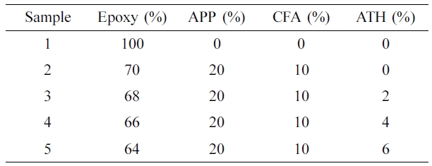
Preparation
of Coatings. To prepare coating samples, epoxy (binder), APP, and CFA
were used as an IFR system and Al(OH)3 as a synergistic agent. The
ratio of APP to CFA was set at 2:1 w/w ratio and the loading content of Al(OH)3
was varied. For the preparation of coatings, APP, CFA, and aluminum
tri-hydroxide were mixed in a dispersion mixer for 3 h. Then this mixture was
mixed in a solution of resin and hardener (2:1) w/w ratio and applied on the
plywood pieces of different dimensions for analysis purpose. The coatings were
applied on plywood with a paint brush at room temperature for two times with
3 h intervals. After, the plywood sheets were dried at room temperature
for two days in the ventilated condition. The thickness of the coating on plywood
was measured to 1.5±0.2 mm by an Elcometer (model A456, USA). The
compositions of the coating are shown in Table 1.
Characterization
Methods. A Nicolet spectrophotometer (model 4700, USA) was used to
perform an FTIR analysis of the samples. The samples were scanned in the range
of 500 to 4500 cm-1. A Carlo Erba (model 1106, Italy) elemental
analyzer was employed for the elemental analysis of the samples.
Limited oxygen index test was performed using an HC-2C oxygen index
instrument (JF-3, China). The coatings were applied on
130 mm×6.5 mm×3.2 mm sized plywood sheets and analyzed according
to ASTM D2863 standard procedure.
UL-94V experiment was conducted on the CZF-2 instrument (China) according
to ASTM D3801 standard procedure. The plywood pieces of 130 mm×13 mm×3.2 mm
dimension were coated with IFR coatings and dried. The 5 specimens of coated
plywood pieces were ignited twice for 10 s, then the burning times were
measured for each sample to give UL-94V rating.
For thermal gravimetric analysis, the weight of each sample was between 4
and 6 mg. This study was conducted on SDT Q-600 (TA instrument, USA) under the
nitrogen flow of 20 mL/min. The temperature range was 30 to 800 oC
with a heating rate of
10 oC/ min.
The combustion behavior of the samples was carried out by a cone calorimeter
(fire testing technology, UK). For this test, 100 mm×100 mm×3 mm
sized plywood sheets were coated at all sides with coating samples and dried
for two days. Then, these plywood sheets were horizontally laid on the sample
holder of the cone calorimeter device. A 35 kW/m2 external heat flux
was exposed on to the coated plywood sheets.
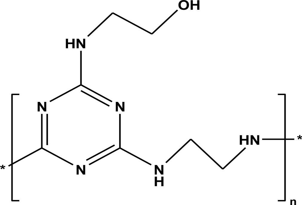
|
Figure 1 Chemical structure of CFA polymer. |
Characterization of CFA. FTIR Analysis of CFA: Figure 2 represents the
FTIR spectrum of the CFA polymer. The peaks at 3435 and 3230 cm-1 are
for νN-H and νO-H symmetric
stretching vibrations respectively. The two peaks of 2930 and 2849 cm-1 are
assigned to C-H vibration in CH2-CH2 group. The
absorption peaks at 1578 and 1362 cm-1 are appeared due to the C=N
vibrations in triazine ring. The other main peaks at 1161 and 1055 cm-1 are
for νC-N and νC-O respectively. The peak at 808 cm-1 has
appeared for νN-H mode vibration.
Also, this spectrum is not showing a peak at 850 cm-1 which
preferentially corresponds to C-Cl bond stretching. The absence of absorption
peak at 850 cm-1 suggests that all the three chlorine atoms are
removed from triazine ring. All of the above peaks confirm that targeted CFA
polymer is formed successfully.
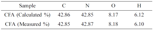
Elemental
Analysis. Table 2 shows the elemental analysis data of the prepared
CFA polymer. From this data, it can be seen that both calculated and measured
values are the same. From the above results, it can be concluded that the
targeted CFA polymer is synthesized successfully.
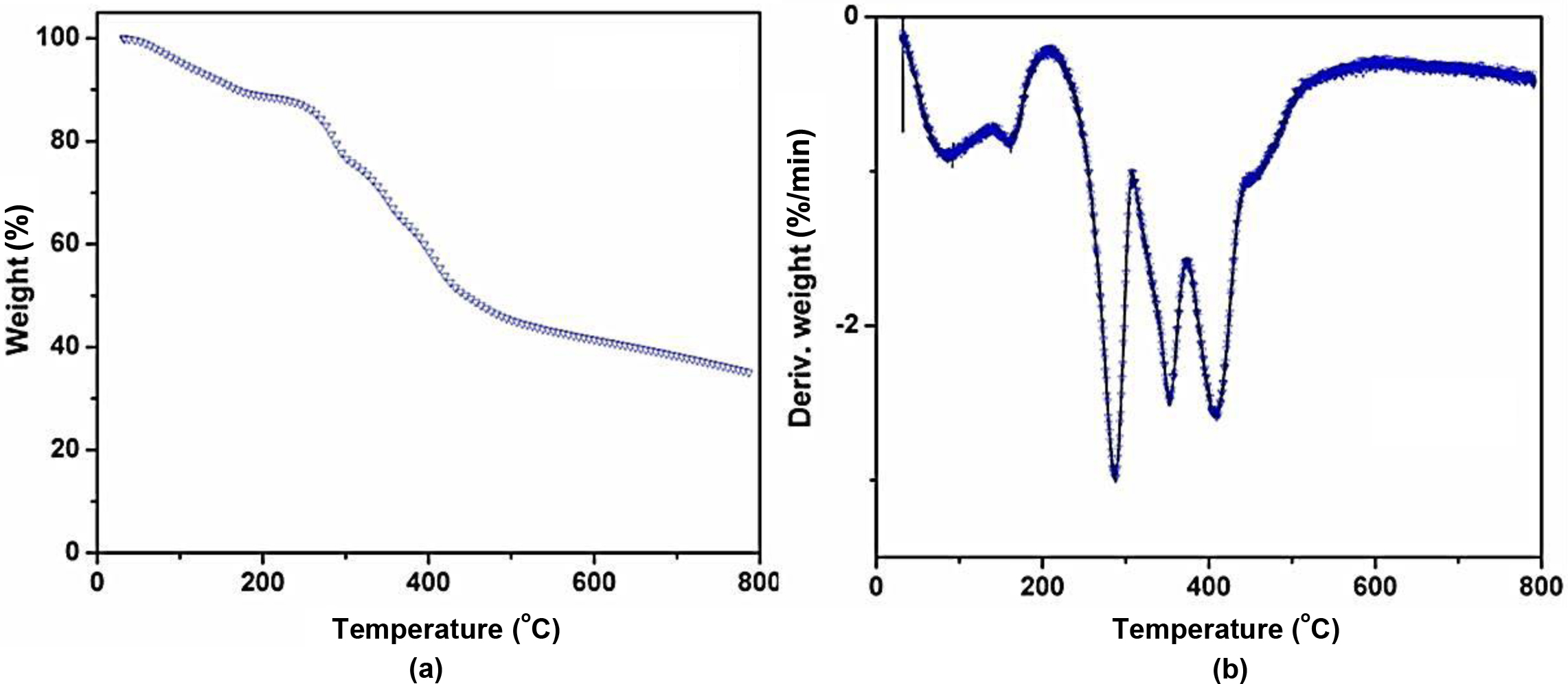
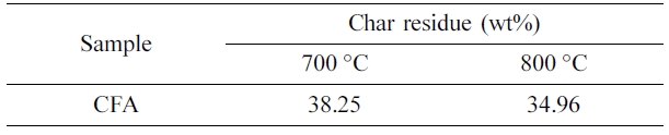
Thermal
Degradation Pattern of CFA. TGA is a
well-known technique for the evaluation of thermal stability and thermal
degradation pattern of a compound. The thermograms (TGA and DTG) of CFA under
nitrogen atmosphere are shown in Figure 3 and Table 3. From these data, it can
be observed that CFA is thermally stable at a higher temperature. The char
residue percentage of the CFA at 700 oC and 800 oC
are 38.25 and 34.96% respectively. The CFA polymer initially showed thermal
degradation at around 70 oC due to the evaporation of solvent
residue (acetone and water). It is also seen that CFA shows three major steps
of thermal degradation at temperature ranges of 260 to 310 oC,
315 to 375 oC, and from 380 to 440 oC
respectively. The degradation of CFA both at 260 to 310 oC and
315 to 375 oC temperatures may be due to the dehydration and
the loss of ammonia from the CFA molecule. The weight loss of CFA at third
degradation stage (380 to 440 oC) is due to the breakage of
macromolecular backbone structure which results in the release of ammonia and
finally forms a char layer. This indicates that the prepared CFA acts as a
charring and foaming agent at high temperatures.
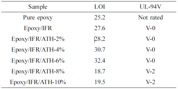
Flame
Retardancy of the Coatings. To evaluate the
flame retardancy of the coatings, the LOI and UL-94V tests were conducted. The
effect of Al(OH)3 on epoxy/IFR coating system is represented in
Table 4. The data shows that pristine epoxy coating is very flammable. The
addition of IFR (APP+CFA) to the epoxy is greatly increased the LOI value from
25.2 to 27.6% and meets the V-0 rating in UL-94V test. It is insisted that APP
involves in thermal degradation and produces acids such as meta-phosphoric acid
and pyro-phosphoric acid which can effectively react with CFA and result in the
formation of a carbon-phosphor char. This char can restrict the transfer of
both oxygen and heat, so flame will stop easily. The CFA preferentially
involves in dehydration reaction as it belongs to poly-hydroxyl containing
triazine polymer. Table 4 also shows that the LOI values effectively increase
for epoxy/IFR/ATH coatings and V-0 rating is accomplished for those. The
addition of ATH at 6% greatly improved the LOI value to 32.4%. It may be due to
the catalytic action of ATH on the condensation reaction between APP and CFA.
The coatings which contain the ATH content more than 8% are unable to increase
the LOI value and can not reach the V-0 rating. The reason may be due to that,
high (more than 8%) loading of ATH can result in incompatibility and
consequently destroys the char layer.
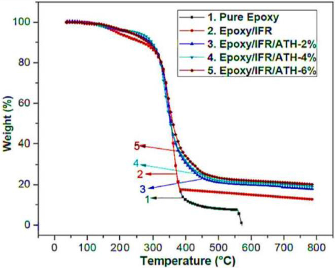
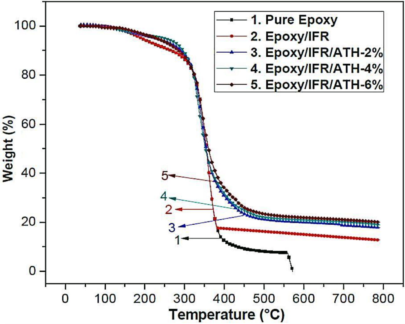
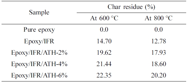
Thermogravimetric
Analysis of Coatings. Thermal
decomposition pattern and thermal stability results of the coating samples of
epoxy/IFR, epoxy/IFR/ATH-2%, epoxy/IFR/ATH-4%, and epoxy/IFR/ATH-6% are shown
in Table 5 and Figure 4. The pure epoxy coating sample is gently flammable and
non-rated in UL-94V test. From the figure, it is seen that all coatings are
showing the same thermal degradation pattern with two main stages. At the first
stage (around 220 oC) of degradation, all the coating samples
have shown a similar pattern due to the partial melting of the IFR material.
All the coating samples are showing major decomposition at the second stage in
the temperature range of 250 to 520 oC. At this stage, the
coating samples result in a great weight loss. While coating samples are
crossing 250 oC, at first the APP involves in decomposition and
generates the water and ammonia gas, and at last, it can be converted into
acids such as meta-phosphoric and pyro-phosphoric acids. These acids
effectively act as a dehydrating agent and remove the water from the CFA
polymer. Figure 1 shows that CFA is a poly-hydroxyl triazine type polymer, so
it can easily cause the dehydration process. This dehydration reaction of APP
and CFA results in the formation of phosphor-carbonaceous protective char. One
highlighting fact is that CFA is also having an abundant amount of nitrogen, so
it also involves in the releasing of ammonia with APP at around 300 oC.
As the ammonia releases, the protective char will become intumescent and so significantly
stops the burning process. From Figure 4, it can be seen that over 520 oC
temperature, epoxy/IFR coating has shown a greater amount of weight loss than
ATH contained coatings. The char residue percentages of the epoxy/IFR,
epoxy/IFR/ATH-2%, epoxy/IFR/ATH-4%, and epoxy/IFR/ATH-6% at 800 oC
are 12.78, 17.93, 18.60, and 20.20% respectively. It confirms that the addition
of ATH remarkably increases the char residue percentage. It may be due to two
reasons; the first one is due to that the ATH makes decomposition very
complicated. A scheme of the chemical reaction between APP and ATH was shown in
Figure 5.26,27 As ATH undergoes thermal decomposition at
180-220 oC, it releases water and forms a dense Al2O3
char. The second reason may be that during decomposition process ATH forms
cross-linkages with IFR system.
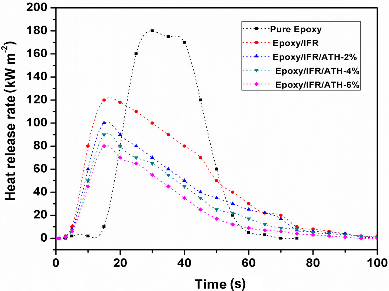
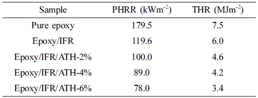
Cone
Calorimeter Analysis. The combustion
behavior of coating samples is evaluated by a cone calorimeter as it can give a
complete profile of flame parameters of a material.
Figure 6 and Table 6 show the heat release rate curves of the coating
materials. From this figure, it can be seen that pure epoxy coating material is
highly flammable. It is burnt very quickly with the releasing of the huge
amount of heat 179.5 kWm‑2 within the short time of 52 s.
The epoxy/IFR coating has shown much lower heat release rate peak than pure
epoxy coating. The addition of the IFR system significantly decreased the PHRR
value of the coating from 179.5 to 119.6 kWm‑2. In addition to
this, the incorporation of ATH at 2, 4, and 6% into the coating system, a great
decrease in the PHRR value than epoxy/IFR coating is obtained. From Figure 6,
it can also be observed that ATH effectively delay the burning process by
decreasing PHRR value. As compared to pure epoxy coating, the PHRR values are
reduced by 34% for epoxy/IFR, 45% for epoxy/IFR/ATH-2%, 51% for epoxy/IFR/ATH-4%, and 57%
for epoxy/IFR/ATH-6%. The decrease in PHRR value concludes that the addition of ATH
shows a synergistic action with IFR to increase the incombustible properties of
the coating material.
It may be due to the formation of a char layer by the synergism of IFR
and ATH. This char prevents the transfer of both heat and oxygen in between
matrix inside part and outside part (flame zone). There is a clear difference
between the PHRR curves of the epoxy/IFR and epoxy/IFR/ATH coatings. During the
combustion process of epoxy/IFR coating, APP and CFA involve in a condensation
reaction to produce a protective char. In the case of combustion of
epoxy/IFR/ATH coatings, ATH involves in the formation of Al2O3
dense protective layer with releasing water and it can form cross-linkages with
IFR system to produce a thick char.
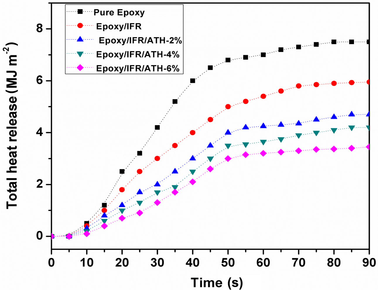
The total heat release rate (THR) values of the coating materials are
presented in Figure 7 and Table 6. This data shows that pure epoxy coating has
the highest THR value than others. Due to the addition of the IFR system into
the coatings, the THR value is reduced from 7.5 to 6 MJ m‑2 (20%
reduction). In addition to this, when the ATH is added to the coating
composition at 2 to 6% the THR values effectively decreased from 7.5 to 4.6,
4.2, and 3.4 MJ m‑2 respectively. It means that 2 to 6% addition of
ATH decreased the THR of the coatings by 39, 44, and 55% respectively. It is
suggested that ATH can strengthen the char and also form a dense Al2O3
protective layer which prevents the flow of heat. Finally, it results in
slowing down the burning process and decreases the heat release from the
sample.
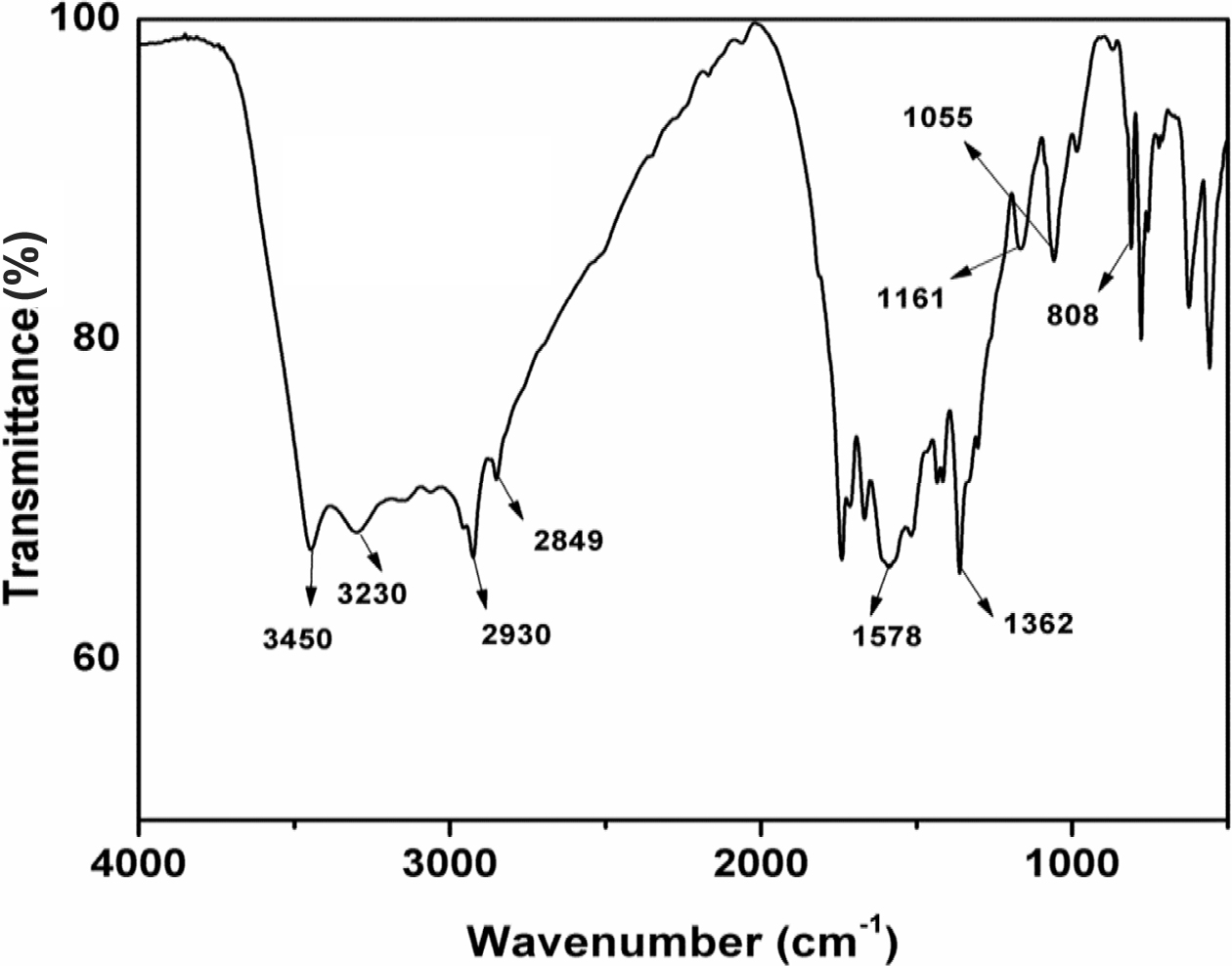
|
Figure 2 FTIR spectrum of CFA polymer. |
|
Figure 3 (a) TGA of CFA polymer; (b) DTG of CFA polymer. |
|
Figure 4 TGA curves of the coating compositions. |
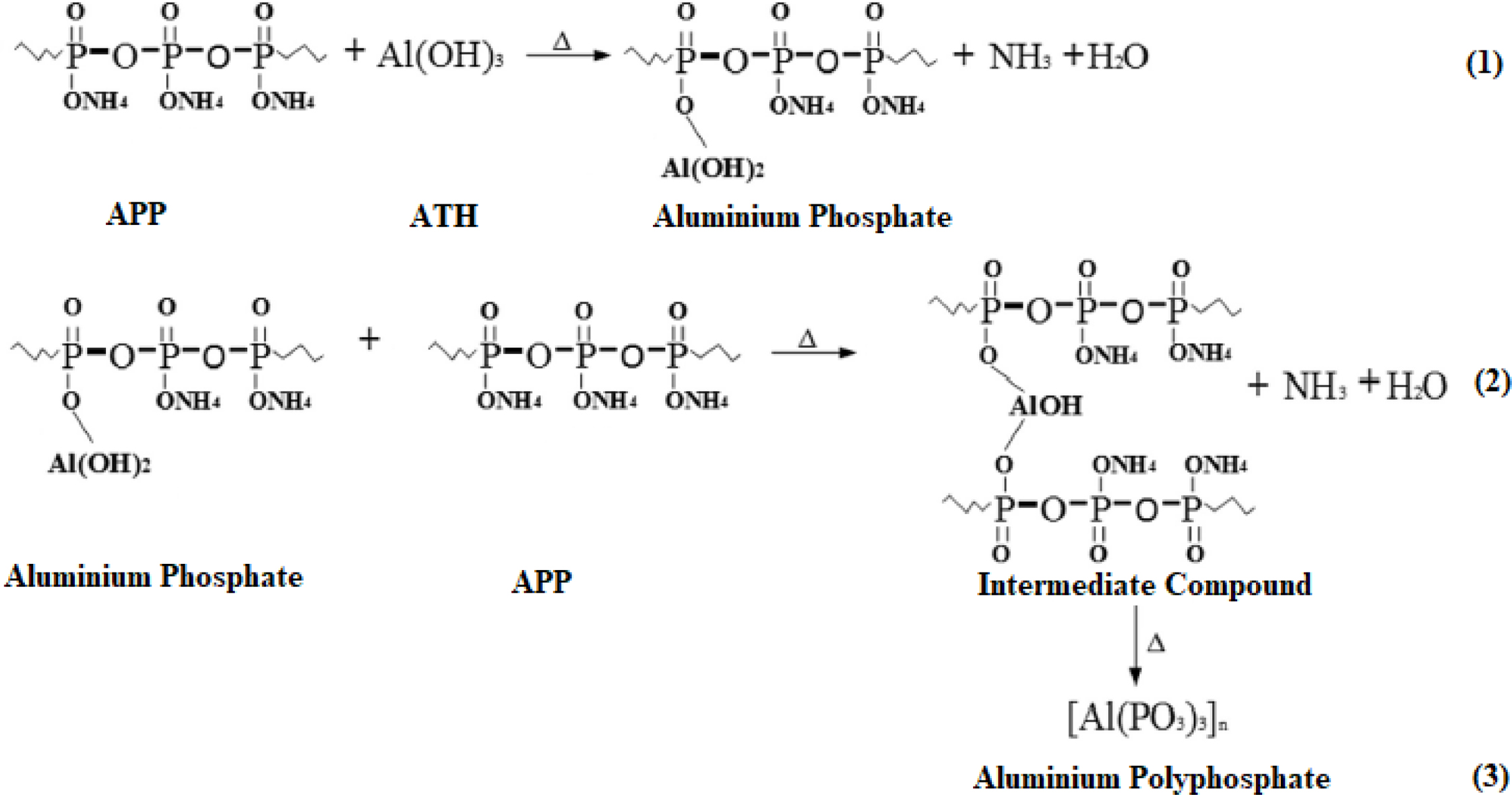
|
Figure 5 A scheme of a chemical reaction between APP and ATH. |
|
Figure 6 Heat release rate curves of the coatings applied on plywood sheets. |
|
Figure 7 Total heat release curves of the coatings applied on plywood sheets. |
In this work, a charring-foaming agent was synthesized successfully and
its structure was characterized by FTIR and elemental analysis. The
APP and CFA are used in epoxy/IFR coating. The ATH was added at different
amount into the coating system and its effects were investigated by LOI, UL-94V,
TGA, and cone calorimeter. The 2 to 6 wt% loading of ATH into coating system
resulted in a great influence on increasing the thermal stability at high
temperatures. The cone calorimeter data confirmed that ATH acts as a synergetic
agent and can effectively decrease the peak heat release rate. The LOI and
UL-94V results indicated that incorporation of ATH remarkably increased the LOI
values with V-0 ratings.
- 1. M. Nikolic, J. M. Lawther, and A. R. Sanadi, J. Coat. Technol. Res., 12, 445 (2015).
-

- 2. A. Temiz, S. Akbas, I. Aydin, and C. Demirkir, Wood Sci. Technol., 50, 179 (2016)
-
- 3. Z. Candan, N. Ayrilmis, and T. Dundar, Wood Res., 57, 651 (2012).
- 4. K. Cheung, “Multi-storey wood frame construction in North America”, in Proceedings of the World Conference on Timber Engineering, Riva del Garda, Italy, June 20-24, 2010.
- 5. A. Ceccotti, C. Sandhaas, M. Okabe, M. Yasumura, C. Minowa, and N. Kawai, Eng. Struct. Dyn., 42, 2003 (2013).
-
- 6. J. W. G. Van De Huilen, A. Ceccotti, Z. Y. Xia, and M. J. He, Procedia Eng., 14, 1621 (2011).
-
- 7. R. X. Cheng and Q. W. Wang, J. Adhes. Sci. Technol., 25, 1715 (2011).
- 8. E. Terzi, S. N. Kartal, R. H. White, K. Shinoda, and Y. Imamura, Eur. J. Wood Prod., 69, 41 (2011).
-
- 9. H. A. Kol, G. Ozbay, L. Kose, and S. Kurt, Bio. Resour., 5, 70 (2010).
- 10. N. Ayrilmis, Z. Candan, and R. White, Holz als Roh-und Werkstoff, 65, 449 (2007).
-
- 11. W. Wang, Z. Zhang, H. Chen, S. F. Zhang, and J. Z. Li, Constr. Build. Mater., 79, 337 (2015).
-
- 12. W. Wang, W. Zhang, S. F. Zhang, and J. Z. Li, Constr. Build. Mater., 65, 151 (2014).
-
- 13. C. S. Chou, S. H. Lin, and C. I. Wang, Adv. Powder Technol., 20, 169 (2009).
-
- 14. C. S. Chuang, K. C. Tsai, M. K. Wang, C. C. Ou, C. H. Ko, and I. L. Shiau, Wood Sci. Technol., 42, 593 (2008).
-
- 15. F. P. Liu and W. M. Zhu, U.S. Patent 5,968,669 (1999).
- 16. M. K. Yalinkilic, W. Y. Su, Y. Imamyra, M. Takahashi, Z. Demirci, and A. C. Yallnkilic, Holz als Roh-und Werkstoff, 56, 347 (1998).
-
- 17. H. Ellis, U.S. Patent 5,130,184 (1992).
- 18. N. Ferre-Huguet, M. Nadal, M. Schuhmacher, and J. L. Domingo, Environ. Sci. Technol., 40, 61 (2006).
-
- 19. W. U. Qiang and Q. U. Baojun, Polym. Degrad. Stab., 74, 255 (2001).
- 20. C. M. Feng, Y. Zhang, S. W. Liu, Z. G. Chi, and J. R. Xu, J. Appl. Polym. Sci., 123, 3208 (2012).
-
- 21. J. F. Dai and B. Li, J. Appl. Polym. Sci., 116, 2157 (2010).
-
- 22. H. Demir, X. E. Arkıs, and S. Ulku, Polym. Degrad. Stab., 89, 478 (2005)
-
- 23. S. Bourbigot, M. Le Bras, R. Delobel, P. Breant, and J. M. Tremillon, Polym. Degrad. Stab., 54, 275 (1996).
-
- 24. L. R. M. Estevao, M. Le Bras, R. Delobel, and R. S. V. Nascimento, Polym. Degrad. Stab., 88, 444 (2015).
-
- 25. L. I. U. Yuan and Q. I. Wang, Polym. Degrad. Stab., 91, 2513 (2006).
- 26. M. Fuzail, G. Shah, and J. Anwar, Iran. Polym. J., 19, 47 (2010).
- 27. N. Wang, D. Xiang, P. Mo, and Y. Lu, Adv. Mater. Res., 652, 485 (2013).
-
- 28. Y. Wang, M. J. Xu, and B. Li, Polym. Degrad. Stab., 131, 20 (2016).
- 29. Y. Li, B. Li, J. Dai, H. Jia, and S. Gao, Polym. Degrad. Stab., 93, 9 (2008).
-
- Polymer(Korea) 폴리머
- Frequency : Bimonthly(odd)
ISSN 0379-153X(Print)
ISSN 2234-8077(Online)
Abbr. Polym. Korea - 2023 Impact Factor : 0.4
- Indexed in SCIE
 This Article
-
2019; 43(6): 831-837
Published online Nov 25, 2019
- 10.7317/pk.2019.43.6.831
- Received on May 5, 2019
- Revised on Jun 18, 2019
- Accepted on Aug 18, 2019
Services
- Full Text PDF
- Abstract
- ToC
- Acknowledgements
Introduction
Experimental
Results and Discussion
Conclusions
- References
Shared
Correspondence to
- Bon Heun Koo
-
School of Materials Science and Engineering, Changwon National University, Changwon, Gyeongnam 51140, Korea *Department of Physics, Abdul Wali Khan University Mardan, Pakistan
- E-mail: bhkoo@changwon.ac.kr
- ORCID:
0000-0003-2867-056X
Hyecheon Building(Room 601), #354, Gangnam-Daero, Gangnam-Gu, Seoul 06242, Korea
TEL : 82-2-568-3860, 561-5203, 569-3860 FAX : 82-2553-6938 E-mail: polymer@polymer.or.kr